No.
(Addr.
Hex)
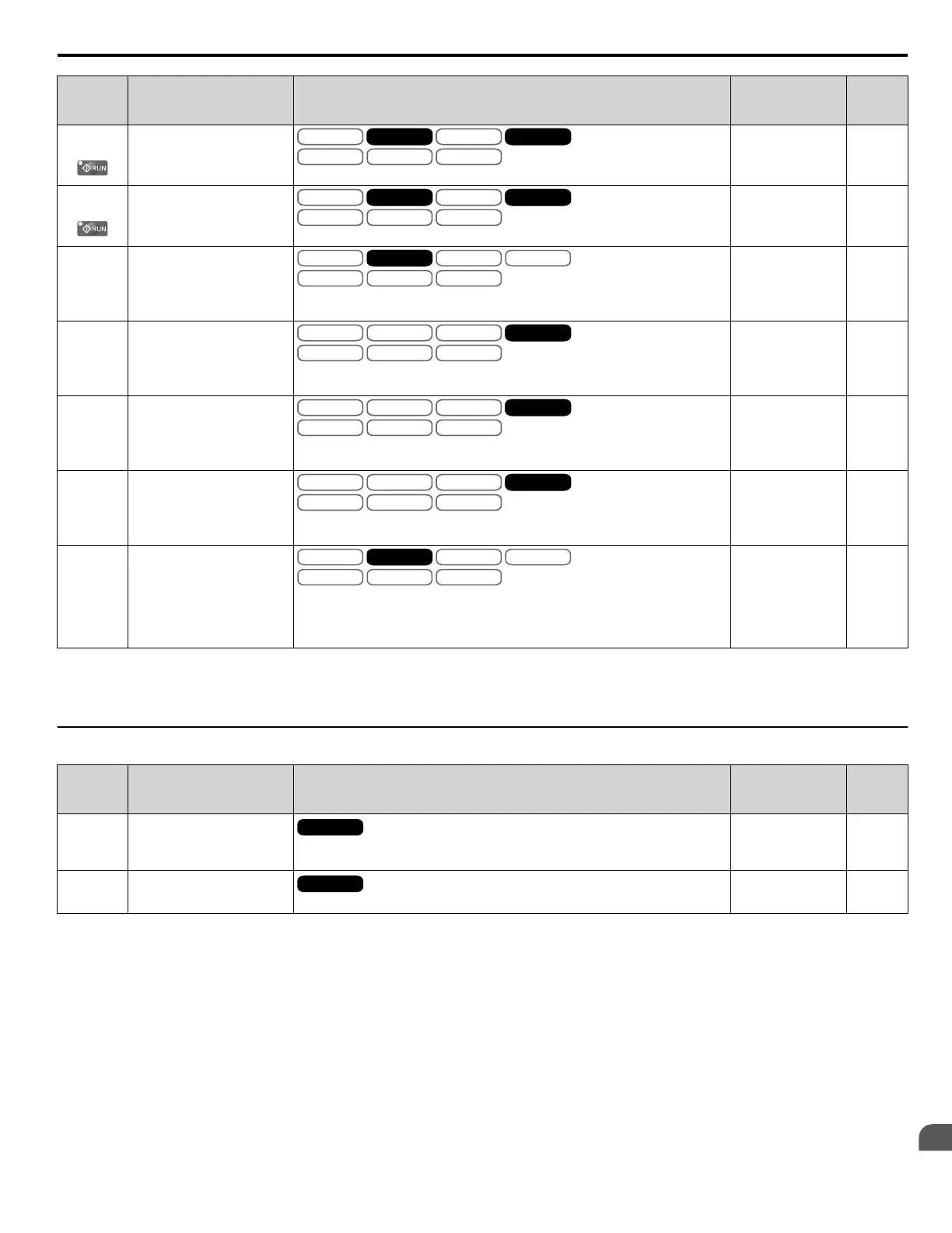
Name Description Values Page
C5-23
(358)
Motor 2 ASR Proportional
Gain 2
V/f
OLV/PM
V/f w PG
AOLV/PM
OLV
CLV/PM
CLVV/f w PG CLVV/f
OLV/PM
V/f w PG
AOLV/PM
OLV
CLV/PM
CLVV/f w PG CLV
Sets the speed control gain 2 of the speed control loop (ASR) for motor 2.
Default:
<5>
Min.: 0.00
Max.: 300.00
<2>
56
C5-24
(359)
Motor 2 ASR Integral Time
2
V/f
OLV/PM
V/f w PG
AOLV/PM
OLV
CLV/PM
CLVV/f w PG CLVV/f
OLV/PM
V/f w PG
AOLV/PM
OLV
CLV/PM
CLVV/f w PG CLV
Sets the integral time 2 of the speed control loop (ASR) for motor 2.
Default:
<5>
Min.: 0.000 s
Max.: 10.000 s
56
C5-25
(35A)
Motor 2 ASR Limit
V/f
OLV/PM
V/f w PG
AOLV/PM
OLV
CLV/PM
CLVV/f w PG
Sets the upper limit for the speed control loop (ASR) for motor 2 as a
percentage of the maximum output frequency (E3-04).
Default: 5.0%
Min.: 0.0
Max.: 20.0
57
C5-26
(35B)
Motor 2 ASR Primary Delay
Time Constant
V/f
OLV/PM
V/f w PG
AOLV/PM
OLV
CLV/PM
CLVCLVV/f
OLV/PM
V/f w PG
AOLV/PM
OLV
CLV/PM
CLVCLV
Sets the filter time constant for the time from the speed loop to the torque
command output used for motor 2.
Default:
<5>
Min.: 0.000 s
Max.: 0.500 s
57
C5-27
(35C)
Motor 2 ASR Gain
Switching Frequency
V/f
OLV/PM
V/f w PG
AOLV/PM
OLV
CLV/PM
CLVCLVV/f
OLV/PM
V/f w PG
AOLV/PM
OLV
CLV/PM
CLVCLV
Sets the frequency for motor 2 used to switch between proportional gain 1 and
2, and between the integral time 1 and 2.
Default: 0.0 Hz
Min.: 0.0
Max.: 400.0
57
C5-28
(35D)
Motor 2 ASR Integral Limit
V/f
OLV/PM
V/f w PG
AOLV/PM
OLV
CLV/PM
CLVCLVV/f
OLV/PM
V/f w PG
AOLV/PM
OLV
CLV/PM
CLVCLV
Sets the ASR integral upper limit for motor 2 as a percentage of rated load
torque.
Default: 400%
Min.: 0
Max.: 400
57
C5-32
(361)
Integral Operation during
Accel/Decel for Motor 2
V/f
OLV/PM
V/f w PG
AOLV/PM
OLV
CLV/PM
CLVV/f w PG
0: Disabled. Integral functions for motor 2 are enabled only during constant
speed.
1: Enabled. Integral functions are always enabled for motor 2, during accel/
decel and during constant speed.
Default: 0
Range: 0, 1
57
<1> Default setting is determined by parameter A1-02, Control Method Selection.
<2> The setting range is 1.00 to 300.00 in CLV and AOLV/PM control modes.
<5> Default setting is determined by parameter E3-01, Motor 2 Control Mode Selection.
u
C6: Carrier Frequency
No.
(Addr.
Hex)
Name Description Values Page
C6-01
(223)
Drive Duty Selection
All Modes
0: Heavy Duty (HD) for constant torque applications.
1: Normal Duty (ND) for variable torque applications.
Default: 1
Range: 0, 1
57
C6-02
(224)
Carrier Frequency Selection
All Modes
1: 2.0 kHz
Default: 1
Range: 1
58
A.5 C: Tuning
YASKAWA ELECTRIC SIEP YEAHHP 01B YASKAWA AC Drive – A1000 HHP Programming Manual
251
A
Parameter List

 Loading...


