Setting 1: Fault Output Is Set
n
L5-04: Fault Reset Interval Time
Determines the amount of time to wait between restart attempts when parameter L5-05 is set to 1.
No. Name Setting Range Default
L5-04 Fault Reset Interval Time 0.5 to 600.0 s 10.0 s
n
L5-05: Fault Reset Operation Selection
No. Name Setting Range Default
L5-05 Fault Reset Operation Selection 0, 1 0
Setting 0: Count Successful Restarts
The drive will continuously attempt to restart. If it restarts successfully, the restart counter is increased. This operation is
repeated each time a fault occurs until the counter reaches the value set to L5-01.
Setting 1: Count Restart Attempts
The drive will attempt to restart using the time interval set to parameter L5-04. A record is kept of the number of attempts to
restart to the drive, regardless of whether those attempts were successful. When the number of attempted restarts exceeds the
value set to L5-01, the drive stops attempting to restart.
u
L6: Torque Detection
The drive provides two independent torque detection functions that trigger an alarm or fault signal when the load is too heavy
(oL), or suddenly drops (UL). These functions are set up using the L6-oo parameters. Program the digital outputs as shown
below to indicate the underload or overload condition to an external device:
Note: When overtorque occurs in the application, the drive may stop due to overcurrent (oC) or overload (oL1). To prevent the drive from stopping,
use torque detection to indicate an overload situation to the controller before oC or oL1 occur. Use undertorque detection to discover
application problems like a torn belt, a pump shutting off, or other similar trouble.
H2-01, H2-02, H2-03
Setting
Description
B Torque detection 1, N.O. (output closes when overload or underload is detected)
17 Torque detection 1, N.C. (output opens when overload or underload is detected)
18 Torque detection 2, N.O. (output closes when overload or underload is detected)
19 Torque detection 2, N.C. (output opens when overload or underload is detected)
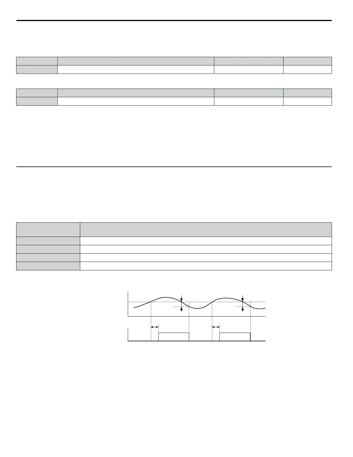
Figure 1.102 and Figure 1.103 illustrate the functions of overtorque and undertorque detection.
Motor current / torque
L6-02/05
10 % hysteresis
Torque detection 1 (NO)
or
Torque detection 2 (NO)
L6-03/06
ON
L6-03/06
10 % hysteresis
ON
Figure 1.102 Overtorque Detection Operation
1.8 L: Protection Functions
148
YASKAWA ELECTRIC SIEP YEAHHP 01B YASKAWA AC Drive – A1000 HHP Programming Manual

 Loading...


