A.15 U: Monitors
Monitor parameters allow the user to view drive status, fault information, and other data concerning drive operation.
u
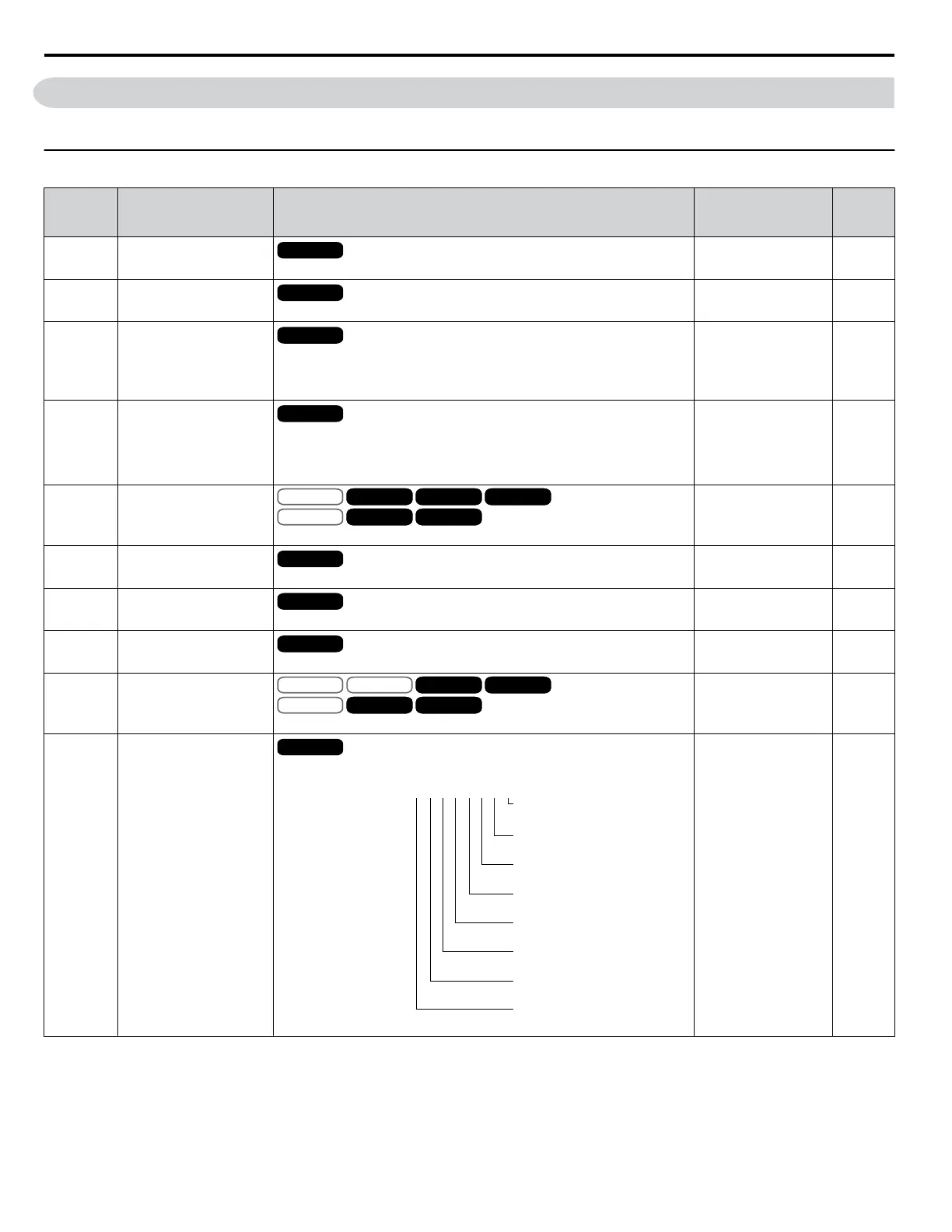
U1: Operation Status Monitors
No.
(Addr.
Hex)
Name Description
Analog Output
Level
Unit
U1-01
(40)
Frequency Reference
All Modes
Monitors the frequency reference. Display units are determined by o1-03.
10 V: Max frequency 0.01 Hz
U1-02
(41)
Output Frequency
All Modes
Displays the output frequency. Display units are determined by o1-03.
10 V: Max frequency 0.01 Hz
U1-03
(42)
Output Current
All Modes
Displays the output current.
Note: This parameter is only available in models CIMR-
Ao4A0930, 4A1200, and A1000 HHP.
10 V: Drive rated
current
<1>
<2>
U1-04
(43)
Control Method
All Modes
0: V/f Control
1: V/f Control with PG
2: Open Loop Vector Control
3: Closed Loop Vector Control
No signal output
available
–
U1-05
(44)
Motor Speed
V/f
OLV/PM
V/f w PG
AOLV/PM
OLV
CLV/PM
CLVV/f w PG
AOLV/PM
OLV
CLV/PM
CLVV/f
OLV/PM
V/f w PG
AOLV/PM
OLV
CLV/PM
CLVV/f w PG
AOLV/PM
OLV
CLV/PM
CLV
Displays the motor speed feedback. Display units are determined by o1-03.
10 V: Max frequency 0.01 Hz
U1-06
(45)
Output Voltage Reference
All Modes
Displays the output voltage.
10 V: 200 Vrms
<3>
0.1 Vac
U1-07
(46)
DC Bus Voltage
All Modes
Displays the DC bus voltage.
10 V: 400 V
<3>
1 Vdc
U1-08
(47)
Output Power
All Modes
Displays the output power (this value is calculated internally).
10 V: Drive rated power
(kW)
<4>
U1-09
(48)
Torque Reference
V/f
OLV/PM
V/f w PG
AOLV/PM
OLV
CLV/PM
CLV
AOLV/PM
OLV
CLV/PM
CLVV/f
OLV/PM
V/f w PG
AOLV/PM
OLV
CLV/PM
CLV
AOLV/PM
OLV
CLV/PM
CLV
Monitors the internal torque reference.
10 V: Motor rated
torque
0.1%
U1-10
(49)
Input Terminal Status
All Modes
Displays the input terminal status.
U1
-
10=
00000000
Digital input 1
(terminal S1 enabled)
Digital input 2
(terminal S2 enabled)
Digital input 3
(terminal S3 enabled)
Digital input 4
(terminal S4 enabled)
Digital input 5
(terminal S5 enabled)
Digital input 6
(terminal S6 enabled)
Digital input 7
(terminal S7 enabled)
Digital input 8
(terminal S8 enabled)
1
1
1
1
1
1
1
1
No signal output
available
–
A.15 U: Monitors
298
YASKAWA ELECTRIC SIEP YEAHHP 01B YASKAWA AC Drive – A1000 HHP Programming Manual

 Loading...


