B.8 Message Examples
Below are some examples of command and response messages.
u
Reading Drive MEMOBUS/Modbus Register Contents
Using the function code 03H (Read), a maximum of 16 MEMOBUS/Modbus registers can be read out at a time.
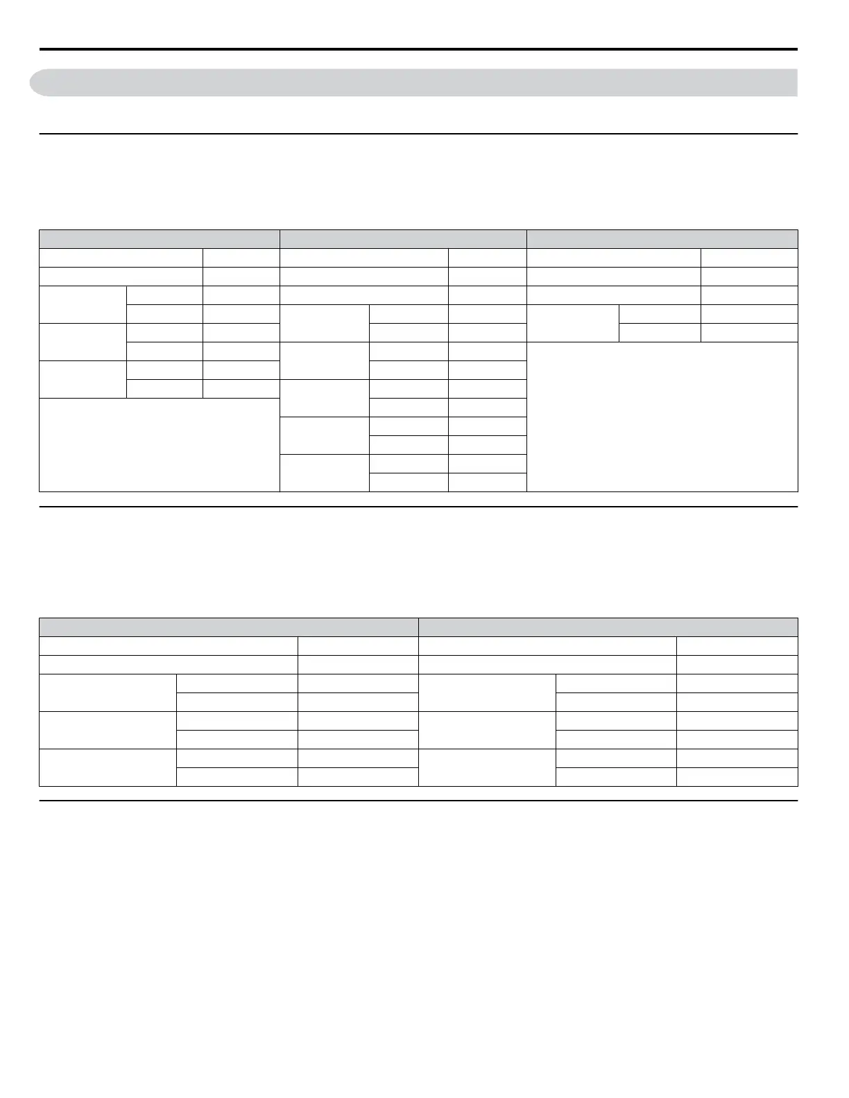
The following table shows message examples when reading status signals, error details, data link status, and frequency
references from the slave 2 drive.
Command Message Response Message (normal) Response Message (fault)
Slave Address 02H Slave Address 02H Slave Address 02H
Function Code 03H Function Code 03H Function Code 83H
Starting No.
Upper 00H Data Quantity 08H Error Code 03H
Lower 20H
1st storage
register
Upper 00H
CRC-16
Upper F1H
Data Quantity
Upper 00H Lower 65H Lower 31H
Lower 04H
Next storage
register
Upper 00H
CRC-16
Upper 45H Lower 00H
Lower F0H
Next storage
register
Upper 00H
Lower 00H
Next storage
register
Upper 01H
Lower F4H
CRC-16
Upper AFH
Lower 82H
u
Loopback Test
Function code 08H performs a loopback test that returns a response message with exactly the same content as the command
message. The response message can be used to check communications between the master and slave. User-defined test code
and data values can also be set.
The following table shows a message example when performing a loopback test with the slave 1 drive.
Command Message Response Message
Slave Address 01H Slave Address 01H
Function Code 08H Function Code 08H
Test Code
Upper 00H
Test Code
Upper 00H
Lower 00H Lower 00H
Data
Upper A5H
Data
Upper A5H
Lower 37H Lower 37H
CRC-16
Upper DAH
CRC-16
Upper DAH
Lower 8DH Lower 8DH
u
Writing to Multiple Registers
Function code 10H allows the user to write multiple drive MEMOBUS/Modbus registers with one message. This process
works similar to reading registers, in that the address of the first register to be written and the data quantity are set in the
command message. The data to be written must be consecutive so that the register addresses are in order, starting from the
specified address in the command message. The data order must be high byte then lower byte.
The following table shows an example of a message where a forward operation has been set with a frequency reference of
60.0 Hz for the slave 1 drive.
If parameter values are changed using the Write command, an Enter command may be necessary to activate or save the data
depending on the setting of H5-11. Refer to H5-11: Communications Enter Function Selection on page 124 and Refer to
Enter Command on page 344 for detailed descriptions.
B.8 Message Examples
326
YASKAWA ELECTRIC SIEP YEAHHP 01B YASKAWA AC Drive – A1000 HHP Programming Manual

 Loading...


