No. Parameter Name Setting Range Default
b3-24 Speed Search Method Selection 0, 1 0
Setting 0: Current Detection Speed Search
Setting 1: Speed Estimation Speed Search
Note: Refer to Current Detection Speed Search (b3-24 = 0) on page 27 and Refer to Speed Estimation Type Speed Search (b3-24 = 1) on page
28 for explanations of the Speed Search methods.
n
b3-25: Speed Search Wait Time
Sets the wait time between Speed Search restarts. Increase the wait time if problems occur with overcurrent, overvoltage, or
if the SEr fault occurs.
No. Name Setting Range Default
b3-25 Speed Search Wait Time 0.0 to 30.0 s 0.5 s
u
b4: Timer Function
The timer function is independent of drive operation and can delay the switching of a digital output triggered by a digital input
signal and help eliminate chattering switch noise from sensors. An on-delay and off-delay can be set separately.
To enable the timer function, set a multi-function input to “Timer Function Input” (H1-oo = 18) and set a multi-function
output to “Timer output” (H2-oo = 12). Only one timer can be used.
n
b4-01, b4-02: Timer Function On-Delay, Off-Delay Time
b4-01 sets the on-delay time for switching the timer output. b4-02 sets the off-delay time for switching the timer output.
No. Name Setting Range Default
b4-01 Timer Function On-Delay Time 0.0 to 3000.0 s 0.0 s
b4-02 Timer Function Off-Delay Time 0.0 to 3000.0 s 0.0 s
n
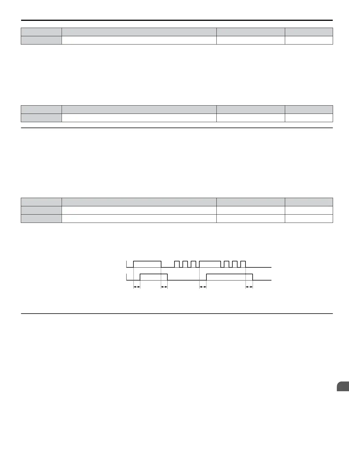
Timer Function Operation
The timer function switches on when the timer function input closes for longer than the value set to b4-01. The timer function
switches off when the timer function input is open for longer than the value set to b4-02. Figure 1.19 illustrates the timer
function operation:
b4-01 b4-02 b4-01 b4-02
Multi-function Contact
On (Closed)
Off (Open)
On (Closed)
Off (Open)
Multi-function Contact
Output: Timer Function
Input: Timer Function
ON ON
ON ON
(H1-□□=18)
(H2-□□=12)
Figure 1.19 Timer Operation
u
b5: PID Control
The drive has a built-in Proportional + Integral + Derivative (PID) controller that uses the difference between the target value
and the feedback value to adjust the drive output frequency to minimize deviation and provide accurate closed loop control
of system variables such as pressure or temperature.
n
P Control
The output of P control is the product of the deviation and the P gain so that it follows the deviation directly and linearly. With
P control, only an offset between the target and feedback remains.
n
I Control
The output of I control is the integral of the deviation. It minimizes the offset between target and feedback value that typically
remains when pure P control is used. The integral time (I time) constant determines how fast the offset is eliminated.
1.2 b: Application
YASKAWA ELECTRIC SIEP YEAHHP 01B YASKAWA AC Drive – A1000 HHP Programming Manual
33
1
Parameter Details

 Loading...


