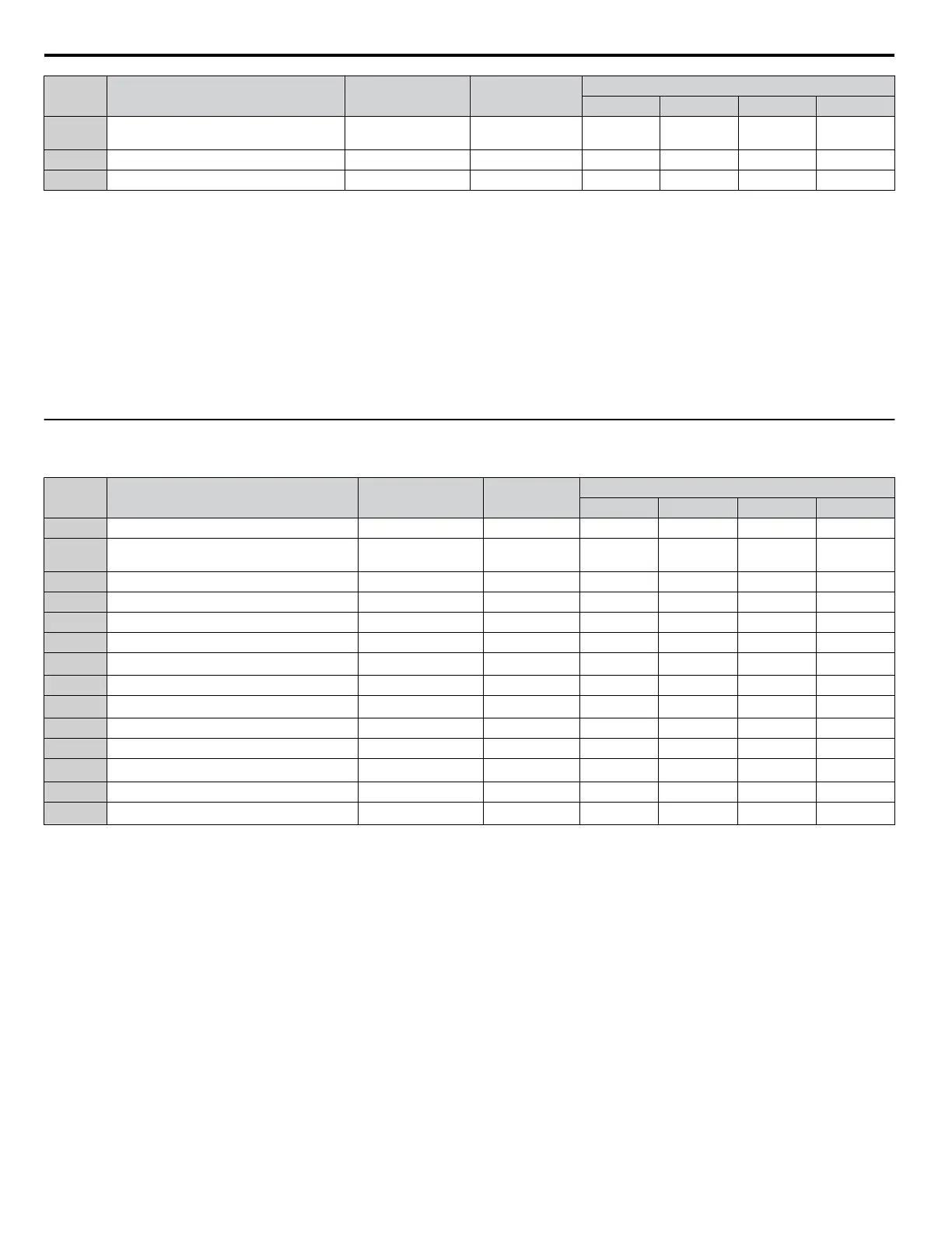
No. Name Setting Range Resolution
Control Modes (A1-02)
V/f (0) V/f w/PG (1) OLV (2) CLV (3)
L8-40
Carrier Frequency Reduction Off Delay
Time
0.00 to 2.00 0.01 s 0.50 0.50 0.50 0.50
o1-03 Digital Operator Display Selection 0 to 3 1 0 0 0 0
o1-04 V/f Pattern Display Unit 0 to 1 1 — — — 0
<1> In AOLV/PM and CLV/PM control modes, the setting units and range are expressed as a percentage (0.0 to 100.0%) instead of in Hz.
<2>
This setting value depends on a Maximum Applicable Motor Capacity in models CIMR-Ao2A0250 to 2A0415, CIMR-Ao4A0139 to 4A1200,
A1000 HHP, and CIMR-Ao5A0099 to 5A0242: 2.00 in Open Loop Vector Control, 0.05 in Closed Loop Vector Control.
<3>
This setting value depends on a Maximum Applicable Motor Capacity: 1000 s in models CIMR-Ao2A0138 to 2A0415, CIMR-Ao4A0139 to
4A1200, A1000 HHP, and CIMR-Ao5A0099 to 5A0242
<4> Default setting is dependent on parameter C6-01, Drive Duty Selection.
<5> In AOLV/PM and CLV/PM control modes, the setting units and range are expressed as a percentage (0.0 to 40.0%) instead of in Hz.
<6> Values shown are specific to 400 V class drives. Multiply the value by 1.4375 for 575 V class drives. Multiply the value by 1.725 for 690 V class
drives.
<7> This setting value depends on a Maximum Applicable Motor Capacity and V/f pattern selection in parameter E1-03.
<8> In AOLV/PM and CLV/PM control modes, the setting units and range are expressed as a percentage (-100.0 to 100.0%) instead of in Hz.
u
E3-01 (Motor 2 Control Mode) Dependent Parameters
Table A.3 E3-01 (Motor 2 Control Mode) Dependent Parameters and Default Values
No. Name Setting Range Resolution
Control Modes (E3-01)
V/f (0) V/f w/PG (1) OLV (2) CLV (3)
C3-21 Motor 2 Slip Compensation Gain 0.0 to 2.5 0.1 0.0 – 1.0 1.0
C3-22
Motor 2 Slip Compensation Primary Delay
Time
0 to 10000 1 ms 2000 – 200 –
C5-21 Motor 2 ASR Proportional Gain 1 0.00 to 300.00 0.01 – 0.20 – 20.00
C5-22 Motor 2 ASR Integral Time 1 0.000 to 10.000 0.001 s – 0.200 – 0.500
C5-23 Motor 2 Proportional Gain 2 0.00 to 300.00 0.01 – 0.02 – 20.00
C5-24 Motor 2 ASR Integral Time 2 0.000 to 10.000 0.001 s – 0.050 – 0.500
C5-26 Motor 2 Carrier Frequency Selection 1 to F –
7
<1>
7
<1>
7
<1>
7
<1>
E3-04 Motor 2 Maximum Output Frequency 40.0 to 150.0 0.1 Hz 60.0 60.0 60.0 60.0
E3-05
Motor 2 Maximum Output Voltage
<2>
0.0 to 510.0 0.2 V 400.0 400.0 400.0 400.0
E3-06 Motor 2 Base Frequency 0.0 to 150.0 0.1 Hz 60.0 60.0 60.0 60.0
E3-07 Motor 2 Mid Output Frequency 0.0 to 150.0 0.1 Hz 3.0 3.0 3.0 0.0
E3-08
Motor 2 Mid Output Frequency Voltage
<2>
0.0 to 510.0 0.2 V 30.0 30.0 22.0 0.0
E3-09 Motor 2 Minimum Output Frequency 0.0 to 150.0 0.1 Hz 1.5 1.5 0.5 0.0
E3-10
Motor 2 Minimum Output Voltage
<2>
0.0 to 510.0 0.2 V 18.0 18.0 4.0 0.0
<1> Default setting is determined by parameters o2-04, Drive Model Selection, and C6-01, Drive Duty Selection.
<2> Values shown here are specific to 400 V class drives. Multiply the values by 1.4375 for 575 V class drives. Multiply the values by 1.725 for 690
V class drives.
A.16 Control Mode Dependent Parameter Default Values
308
YASKAWA ELECTRIC SIEP YEAHHP 01B YASKAWA AC Drive – A1000 HHP Programming Manual

 Loading...


