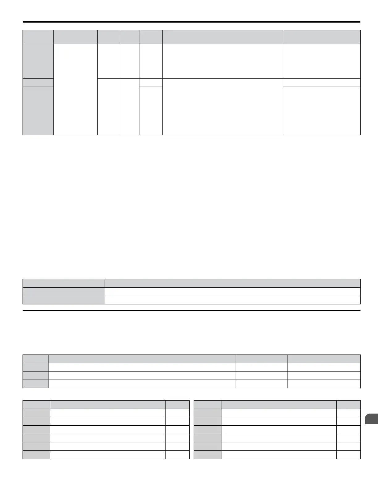
Condition
Freq. Ref.
Source
d4-03 d4-05 d4-01 Operation Frequency Saved
8
Other (analog
comm, etc.)
0 1 --
• Accelerates (increases the bias) while the Up 2
terminal is closed.
• Decelerates (decreases the bias) while Down 2 is
closed.
• Otherwise operates at the frequency reference
Not saved
9
Value
other
than 0
--
0 • When Up 2 is enabled, drive accelerates to the
frequency reference plus d4-03 (increases the bias
for d4-03).
• When Down 2 is enabled, drive decelerates to the
frequency reference minus d4-03 (decreases the
bias for d4-03).
• If the frequency reference changes for more than
d4-07 during accel/decel, bias value is held until the
output frequency meets the reference (speed agree).
Not saved
10 1
If the bias is constant for 5 s, it is
saved to parameter d4-06. The
frequency reference cannot be
overwritten, so only the bias is
saved.
Setting 77: ASR Gain Switch
Switches the ASR gain between the values set to C5-01 and C5-03. The gain set to C5-03 is enabled when the terminal is
closed, and C5-01 is enabled when the terminal reopens. Refer to C5-01, C5-03/C5-02, C5-04: ASR Proportional Gain 1, 2/
ASR Integral Time 1, 2 on page 54 for a more detailed description.
Setting 78: External Torque Reference Polarity Inversion
Reverses the direction of the torque reference when the terminal closes. Refer to d5: Torque Control on page 67 and Setting
the Torque Reference, Speed Limit, and Torque Compensation Values on page 68 for details.
Setting 7E: Forward/Reverse Detection (for V/f Control with Simple PG Feedback)
Determines the motor rotation direction for V/f Control with Simple PG feedback (A1-02 = 0 and H6-01 = 3). If the input is
open, the speed feedback signal is considered to be forward. If the input is closed, it is considered to be reverse. Refer to H6:
Pulse Train Input/Output on page 125.
Setting 90 to 97: DriveWorksEZ Digital Input 1 to 8
These settings are for digital input functions used in DriveWorksEZ. Changing these settings is not typically required.
Setting 9F: DriveWorksEZ Disable
This function is used to enable or disable a DriveWorksEZ program in the drive. An input programmed for this function is
effective only if A1-07 = 2.
Status Description
Open DriveWorksEZ enabled
Closed DriveWorksEZ disabled
u
H2: Multi-Function Digital Outputs
n
H2-01 to H2-03: Terminal M1-M2, P1-PC, and P2-PC Function Selection
The drive has three multi-function output terminals. Table 1.40 lists the functions available for theses terminals using H2-01,
H2-02, and H2-03.
No. Parameter Name Setting Range Default
H2-01 Terminal M1-M2 Function Selection (relay) 0 to 192 0: During run
H2-02 Terminal P1-PC Function Selection (photocoupler) 0 to 192 1: Zero Speed
H2-03 Terminal P2–PC Function Selection (photocoupler) 0 to 192 2: Speed agree 1
Table 1.40 Multi-Function Digital Output Terminal Settings
Setting Function Page
0 During Run 106
1 Zero Speed 106
2 Speed Agree 1 107
3 User-Set Speed Agree 1 107
4 Frequency Detection 1 108
5 Frequency Detection 2 108
Setting Function Page
6 Drive Ready 108
7 DC Bus Undervoltage 109
8 During Baseblock (N.O.) 109
9 Frequency Reference Source 109
A Run Command Source 109
B Torque Detection 1 (N.O.) 109
1.7 H: Terminal Functions
YASKAWA ELECTRIC SIEP YEAHHP 01B YASKAWA AC Drive – A1000 HHP Programming Manual
105
1
Parameter Details

 Loading...


