2.3 Drive Alarms, Faults, and Errors
u
Types of Alarms, Faults, and Errors
Check the digital operator for information about possible faults if the drive or motor fails to operate.
If problems occur that are not covered in this manual, contact the nearest Yaskawa representative with the following
information:
• Drive model
• Software version
• Date of purchase
• Description of the problem
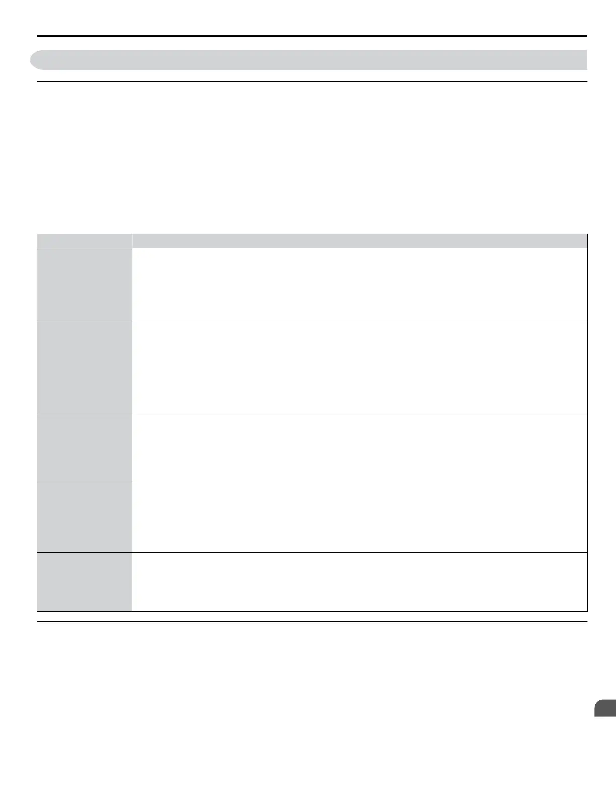
Table 2.4 contains descriptions of the various types of alarms, faults, and errors that may occur while operating the drive.
Table 2.4 Types of Alarms, Faults, and Errors
Type Drive Response
Faults
When the drive detects a fault:
• The digital operator displays text indicating the specific fault and the ALM indicator LED remains lit until the fault is reset.
• The fault interrupts drive output and the motor coasts to a stop.
• Some faults allow the user to select the stopping method when the fault occurs.
• Fault output terminals MA-MC will close, and MB-MC will open.
The drive will remain inoperable until the fault is cleared. Refer to Fault Reset Methods on page 225.
Minor Faults and
Alarms
When the drive detects an alarm or a minor fault:
• The digital operator displays text indicating the specific alarm or minor fault, and the ALM indicator LED flashes.
• The drive continues running the motor, although some alarms allow the user to select a stopping method when the alarm
occurs.
•
A multi-function contact output set to be tripped by a minor fault (H2- oo = 10) closes. If the output is set to be tripped
by an alarm, the contact will not close.
• The digital operator displays text indicating a specific alarm and the ALM indicator LED flashes.
Remove the cause of the problem to reset a minor fault or alarm.
Operation Errors
An operation error occurs when parameter settings conflict or do not match hardware settings (such as with an option card).
When the drive detects an operation error:
• The digital operator displays text indicating the specific error.
• Multi-function contact outputs do not operate.
The drive will not operate the motor until the error has been reset. Correct the settings that caused the operation error to clear
the error.
Tuning Errors
Tuning errors occur while performing Auto-Tuning.
When the drive detects a tuning error:
• The digital operator displays text indicating the specific error.
• Multi-function contact outputs do not operate.
• Motor coasts to stop.
Remove the cause of the error and repeat the Auto-Tuning process.
Copy Function Errors
Copy Function Errors occur when using the digital operator or the USB Copy Unit to copy, read, or verify parameter settings.
• The digital operator displays text indicating the specific error.
• Multi-function contact outputs do not operate.
Pressing any key on the digital operator will clear the fault. Investigate the cause of the problem (such as model incompatibility)
and try again.
u
Alarm and Error Displays
n
Faults
Table 2.5 gives an overview of possible fault codes. Conditions such as overvoltages can trip faults and alarms. It is important
to distinguish between faults and alarms to determine the proper corrective actions.
When the drive detects a fault, the ALM indicator LED lights, the fault code appears on the digital operator, and the fault
contact MA-MB-MC triggers. An alarm is present if the ALM LED blinks and the fault code on the digital operator flashes.
Refer to Minor Faults and Alarms on page 181 for a list of alarm codes.
2.3 Drive Alarms, Faults, and Errors
YASKAWA ELECTRIC SIEP YEAHHP 01B YASKAWA AC Drive – A1000 HHP Programming Manual
179
2
Troubleshooting

 Loading...


