Digital Operator
Display
Name Page
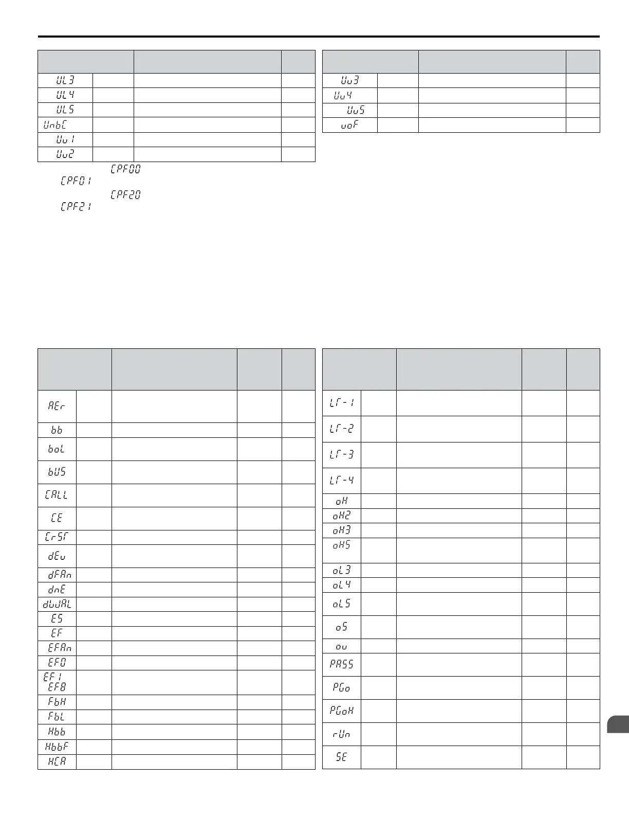
UL3 Undertorque Detection 1 200
UL4 Undertorque Detection 2 200
UL5 Mechanical Weakening Detection 2 200
<3>
UnbC Current Unbalance 200
Uv1 Undervoltage 200
Uv2 Control Power Supply Undervoltage 201
Digital Operator
Display
Name Page
Uv3 Soft Charge Circuit Fault 201
<3>
Uv4 Gate Drive Board Undervoltage 201
Uv5 MC/FAN power malfunction 201
voF Output Voltage Detection Fault 201
<1>
Displayed as when occurring at drive power up. When one of the faults occurs after successfully starting the drive, the display will show
.
<2>
Displayed as when occurring at drive power up. When one of the faults occurs after successfully starting the drive, the display will show
.
<3>
Detected in models CIMR-Ao4A0930 and 4A1200.
<4> Available in drive software versions 1015 and later for standard A1000 and 1012 and later for A1000 HHP models.
n
Minor Faults and Alarms
Refer to Table 2.6 for an overview of possible alarm codes. Conditions such as overvoltages can trip faults and alarms. It is
important to distinguish between faults and alarms to determine the proper corrective actions.
When the drive detects an alarm, the ALM indicator LED blinks and the alarm code display flashes. Most alarms trigger a
digital output programmed for alarm output (H2-oo = 10). A fault (not an alarm) is present if the ALM LED lights without
blinking. Refer to Faults on page 179 for information on fault codes.
Table 2.6 Minor Fault and Alarm Displays
Digital Operator
Display
Name
Minor Fault
Output
(H2-oo =
10)
Page
AEr
SI-T Station Number Setting
Error (CC-Link, CANopen,
MECHATROLINK-II)
YES 203
bb Drive Baseblock No output 203
boL
Braking Transistor Overload
Fault
YES 203
bUS
Option Card Communications
Error
YES 203
CALL
Serial Communication
Transmission Error
YES 204
CE
MEMOBUS/Modbus
Communication Error
YES 204
CrST Cannot Reset YES 204
dEv
Excessive Speed Deviation
(for Control Mode with PG)
YES 204
dFAn Abnormal Diode Module Fan YES 205
dnE Drive Disabled YES 205
dWAL DriveWorksEZ Alarm YES 187
E5 SI-T3 Watchdog Timer Error YES 187
EF Run Command Input Error YES 205
EFAn Abnormal Panel Fan YES 205
EF0 Option Card External Fault YES 205
to EF1 to
EF8
External Fault
(input terminal S1 to S8)
YES 206
FbH Excessive PID Feedback YES 206
FbL PID Feedback Loss YES 206
Hbb
Safe Disable Signal Input
<3>
YES 206
HbbF
Safe Disable Signal Input
<3>
YES 207
HCA Current Alarm YES 207
Digital Operator
Display
Name
Minor Fault
Output
(H2-oo =
10)
Page
LT-1 Cooling Fan Maintenance Time
No output
<1>
207
LT-2 Capacitor Maintenance Time
No output
<1>
207
LT-3
Soft Charge Bypass Relay
Maintenance Time
No output
<1>
208
LT-4 IGBT Maintenance Time (50%)
No output
<1>
208
oH Heatsink Overheat YES 208
oH2 Drive Overheat YES 208
oH3 Motor Overheat YES 208
<2>
oH5 Motor Overheat (NTC Input) YES 208
oL3 Overtorque 1 YES 209
oL4 Overtorque 2 YES 209
oL5
Mechanical Weakening
Detection 1
YES 209
oS
Overspeed
(for Control Mode with PG)
YES 209
ov Overvoltage YES 210
PASS
MEMOBUS/Modbus Test Mode
Complete
No output 210
PGo
PG Disconnect
(for Control Mode with PG)
YES 210
PGoH
PG Hardware Fault
(when using PG-X3)
YES 210
rUn
During Run 2, Motor Switch
Command Input
YES 210
SE
MEMOBUS/Modbus Test Mode
Fault
YES 211
2.3 Drive Alarms, Faults, and Errors
YASKAWA ELECTRIC SIEP YEAHHP 01B YASKAWA AC Drive – A1000 HHP Programming Manual
181
2
Troubleshooting

 Loading...


