Parameter H3-04 sets the level of the selected input value that is equal to 0 V input at terminal A1 (bias).
Use both parameters to adjust the characteristics of the analog input signal to terminal A1.
No. Name Setting Range Default
H3-03 Terminal A1 Gain Setting -999.9 to 999.9% 100.0%
H3-04 Terminal A1 Bias Setting -999.9 to 999.9% 0.0%
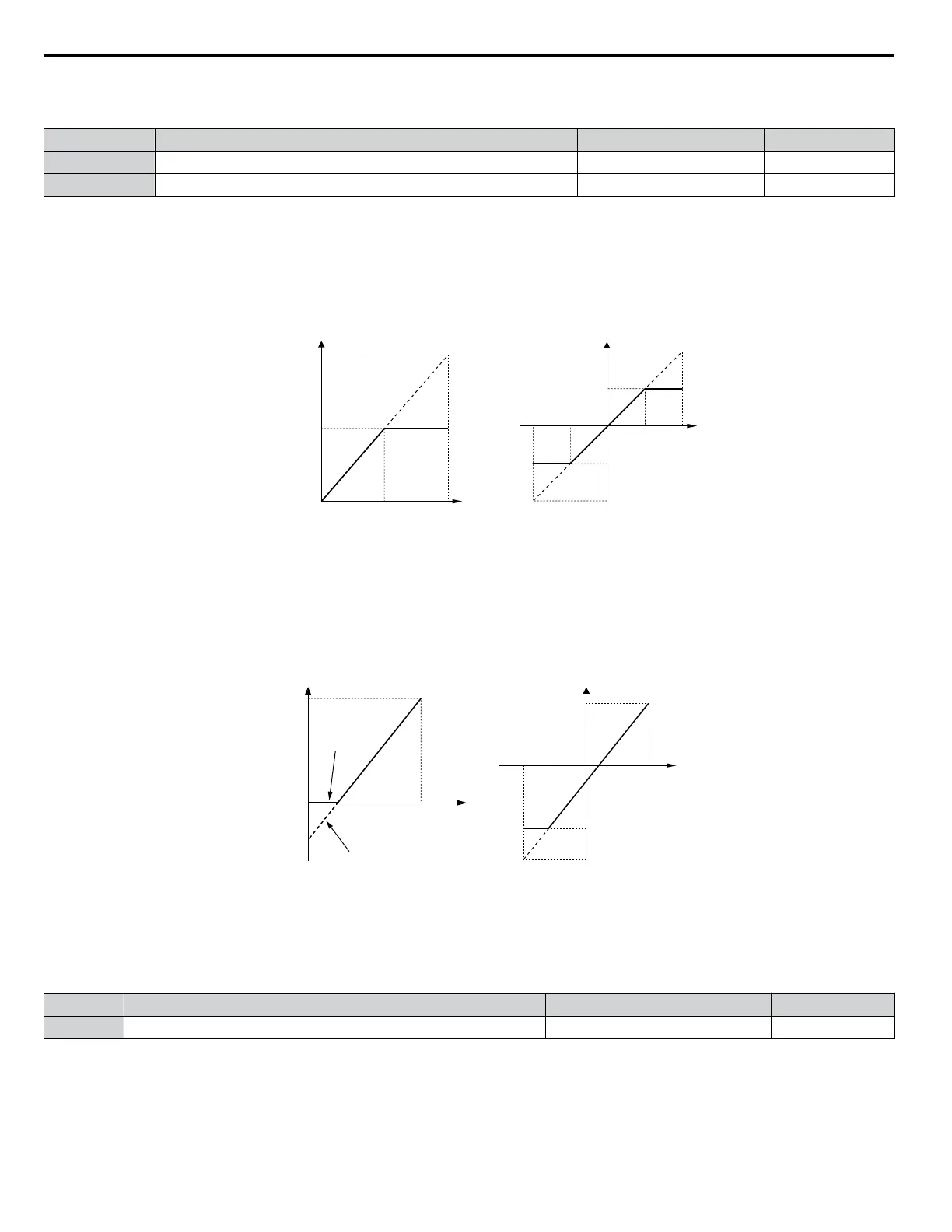
Setting Examples
• Gain H3-03 = 200%, bias H3-04 = 0, terminal A1 as frequency reference input (H3-02 = 0):
A 10 Vdc input is equivalent to a 200% frequency reference and 5 Vdc is equivalent to a 100% frequency reference. Since
the drive output is limited by the maximum frequency parameter (E1-04), the frequency reference will be equal to E1-04
above 5 Vdc.
100%
-100%
5 V
10 V
-5 V-10 V
E1-04
E1-04
H3-01 = 0 H3-01 = 1
0 V
10 V5 V
0 V
Gain = 200 % Gain = 200 %
100 %
Frequency
reference
Bias = 0 %
E1-04
Gain = -200 %
Figure 1.75 Frequency Reference Setting by Analog Input with Increased Gain
• Gain H3-03 = 100%, bias H3-04 = -25%, terminal A1 as frequency reference input:
An input of 0 Vdc will be equivalent to a -25% frequency reference.
When parameter H3-01 = 0, the frequency reference is 0% between 0 and 2 Vdc input.
When parameter H3-01 = 1, the motor will rotate in reverse between -10 and 2 Vdc input.
2.0 V
10 V
-6.0 V-10 V
E1-04
0
-100%
-150%
2.0 V 10 V
100 %
Frequency
reference
-25%
-25%
H3-01 = 0
H3-01 = 1
H3-01 = 0 H3-01 = 1
100%
Analog Input
Voltage
Analog Input
Voltage
Figure 1.76 Frequency Reference Setting by Analog Input with Negative Bias
n
H3-05: Terminal A3 Signal Level Selection
Selects the input signal level for analog input A3. Refer to Multi-Function Analog Input Terminal Settings on page 118 for
a list of functions and descriptions.
No. Name Setting Range Default
H3-05 Terminal A3 Signal Level Selection 0, 1 0
Setting 0: 0 to 10 Vdc
The input level is 0 to 10 Vdc. See the explanation provided for H3-01. Refer to Setting 0: 0 to 10 Vdc on page 115.
Setting 1: -10 to 10 Vdc
The input level is -10 to 10 Vdc. See the explanation provided for H3-01. Refer to Setting 1: -10 to 10 Vdc on page 115.
1.7 H: Terminal Functions
116
YASKAWA ELECTRIC SIEP YEAHHP 01B YASKAWA AC Drive – A1000 HHP Programming Manual

 Loading...


