3.8 Main Circuit Wiring
YASKAWA ELECTRIC
SIEP C710636 02B YASKAWA U1000 Technical Manual 91
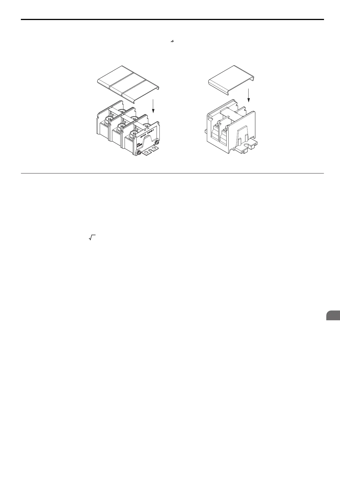
Attach the protective covers after wiring the main circuit terminals, p1, and n1 terminals on models 20104 to
20248, 40096 to 40590, and the p1, n1, p2, n2, r1, 1, and t1 terminals on models 40720 to 40930.
Figure 3.31 shows an example of a main circuit protective cover for model 20104.
Figure 3.32
Figure 3.31 Protective Cover (20104)
◆ Main Circuit Wire Gauges and Tightening Torque
Select the appropriate wires and crimp terminals from Table 3.5 through Table 3.8.
Note: Wire gauge recommendations based on drive continuous current ratings (ND) using 75°C 600 Vac vinyl-sheathed wire assuming
ambient temperature within 40°C and wiring distance less than 100 m.
• Consider the amount of voltage drop when selecting wire gauges. Increase the wire gauge when the voltage drop is
greater than 2% of motor rated voltage. Ensure the wire gauge is suitable for the terminal block. Use the following
formula to calculate the amount of voltage drop:
Line drop voltage (V) = × wire resistance (Ω/km) × wire length (m) × motor rated current (A) × 10
-3
• Refer to UL Standards Compliance on page 594 for information on UL compliance.
The wire gauges listed in the following tables are Yaskawa recommendations. Refer to local codes for proper wire gauge
selections.
Main circuit terminal
Terminals p1, n1
SIEP_C710636_02B_1_0.book 91 ページ 2015年11月25日 水曜日 午後4時56分

 Loading...


