Operating the XtraDrive Using XtraWare
¾ To set the interpolation method:
1. Click in, or tab to, the Curve Shape field.
2. Click the
icon that is displayed in the Curve Shape field.
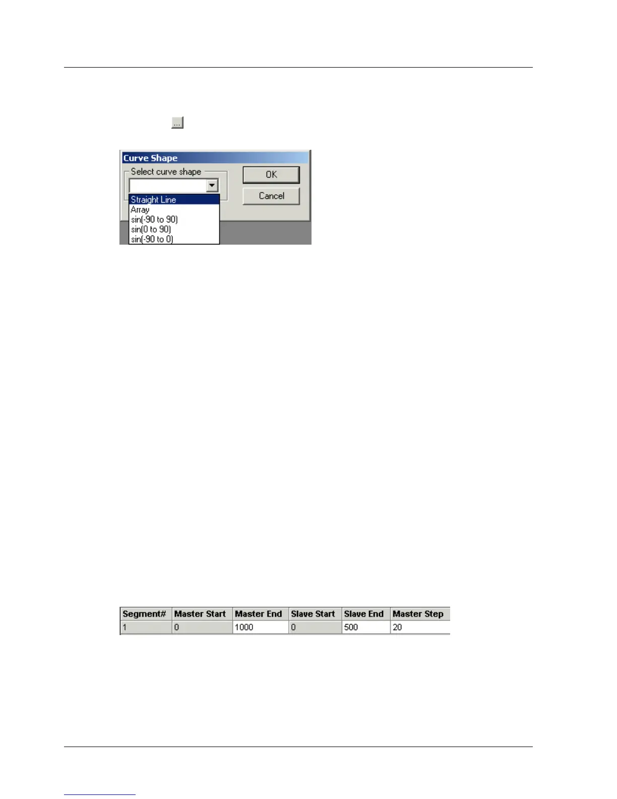
The Curve Shape window is displayed.
Figure 35: Curve Shape Window
3. Select a curve shape from the drop-down menu:
Straight Line: Points will be generated by interpolation to join the
start and end points with a straight line.
Array: Instead of selecting a shape for XtraWare to generate by
interpolation, you can specify all the points directly. See section
4.9.5.6, Specifying an Array.
sin(-90 to 90), sin(0 to 90), sin(-90 to 0): Points will be
generated by interpolation to join the start and end points with the
required section of a sinusoidal graph.
4. Click OK.
A new line for the next segment is displayed in the Position Setting tab
with the Master Start and Slave Start fields filled in automatically.
5. Continue filling in the table until every segment in the profile has been
defined.
4.9.5.6. Specifying an Array
Instead of specifying a curve shape along which points must be
interpolated, XtraWare allows you to specify each point directly. You can
either specify the points within the XtraWare interface, or you can import a
file created in a spreadsheet program.
The number of points to be specified is dependent on the Master Step
setting. For example, consider the following specification.
Figure 36: Example of End Point Specification
The length of the segment is 1000 master counts and the Master Step is 20.
The number of points in the segment, including the start and end points is
thus 51.
XtraWare User Manual 53
 Loading...