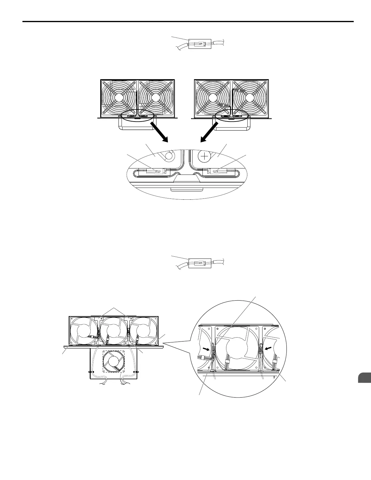
Protective tube
2.
Insert the connector for fan B2 and guide the lead wire for fan B2 so the cable hook holds it in place.
Insert the connector for fan B1.
Connector for fan B1
Fan B1
Fan B2
Connector for fan B2
Figure 2.19 Cooling Fan Wiring: 5A0125 and 5A0145
3.
Make sure that the protective tube does not stick out beyond the fan guard.
n
Cooling Fan Wiring: 5A0192 and 5A0242
1.
Position the protective tube so the fan connector sits in the center of the protective tube.
Protective tube
2.
In the space between fans 1 and 2, place the fan connector for fan B2 in front of the fan connector for fan B1.
3.
Place the connector for fan B3 between fans B2 and B3.
Cable cover
Fan B3
Fan B2
Connector for fan B3
Connector for fan B1
Connector for fan B2
Fan B1
Figure 2.20 Cooling Fan Wiring: 5A0192 and 5A0242
4.
Double-check the relay connector to ensure it is properly connected.
5.
Reattach the cable cover to its original position and tighten the screws so the fan guard holds the cable cover in place.
Note: Do not pinch the fan cable between parts when reassembling the fan unit.
2.5 Drive Cooling Fans
YASKAWA SIEP YAIZ1U 03B YASKAWA AC Drive – Z1000 Programming Manual
177
2
Periodic Inspection &
Maintenance

 Loading...


