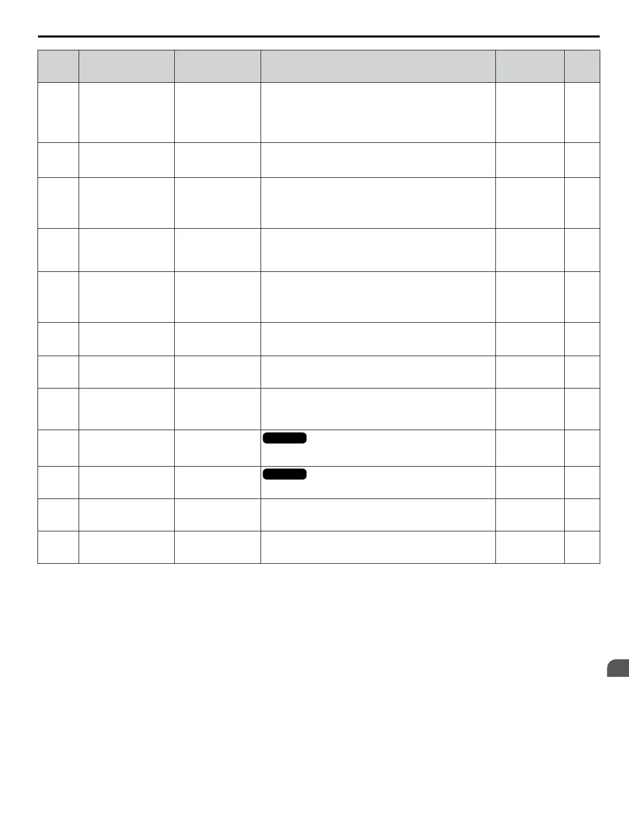
No.
(Addr.
Hex)
Name LCD Display Description Values Page
L3-05
(493)
Stall Prevention
Selection during Run
StallP Run Sel
0: Disabled
1: Decel time
2: Decel time 2
0: Disabled. Drive runs at a set frequency. A heavy load may
cause speed loss.
1: Decel time 1. Uses the deceleration time set to C1-02 while
Stall Prevention is performed.
2: Decel time 2. Uses the deceleration time set to C1-04 while
Stall Prevention is performed.
Default: 1
Range: 0 to 2
107
L3-06
(494)
Stall Prevention Level
during Run
StallP Run Level
Enabled when L3-05 is set to 1 or 2. 100% is equal to the drive
rated current.
Default:
<1>
Min.: 30%
Max.: 150%
<1>
107
L3-11
(4C7)
Overvoltage
Suppression Function
Selection
OV Inhibit Sel
0: Disabled
1: Enabled
Enables or disables the ov suppression function, which allows
the drive to change the output frequency as the load changes to
prevent an ov fault.
0: Disabled
1: Enabled
Default: 0
Range: 0, 1
108
L3-17
(462)
Target DC Bus Voltage
for Overvoltage
Suppression and Stall
Prevention
DC Bus Reg Level
Sets the desired value for the DC bus voltage during overvoltage
suppression and Stall Prevention during deceleration.
Default: 1063.8
Vdc
<3>
Min.: 431.3
Max.: 1150.0
108
L3-20
(465)
DC Bus Voltage
Adjustment Gain
DC Bus P Gain
Determines the proportional gain used by overvoltage
suppression (L3-11 = 1), Single drive KEB 2 (L2-29 = 1), KEB
Ride-Thru 2 (H1-oo = 7A or 7B), and Intelligent Stall
Prevention during Deceleration (L3-04 = 2) to control the DC
bus voltage in OLV/PM.
Default:
<4>
Min.: 0.00
Max.: 5.00
109
L3-21
(466)
Accel/Decel Rate
Calculation Gain
Acc/Dec P Gain
Sets the proportional gain used to calculate the deceleration rate
during KEB Ride-Thru, ov suppression function, and Stall
Prevention during deceleration (L3-04 = 2).
Default:
<4>
Min.: 0.00
Max.: 200.00
109
L3-22
(4F9)
Deceleration Time at
Stall Prevention during
Acceleration
PM Acc Stall P T
Sets the deceleration time used for Stall Prevention during
acceleration in OLV/PM.
Default: 0.0 s
Min.: 0.0
Max.: 6000
106
L3-23
(4FD)
Automatic Reduction
Selection for Stall
Prevention during Run
CHP Stall P Sel
0: Lv1 set in L3-06
1: Autom. Reduction
0: Sets the Stall Prevention level set in L3-04 that is used
throughout the entire frequency range.
1: Automatic Stall Prevention level reduction in the constant
output range. The lower limit value is 40% of L3-06.
Default: 0
Range: 0, 1
108
L3-24
(46E)
Motor Acceleration
Time for Inertia
Calculations
Mtr Accel Time
OLV/PMOLV/PM
Sets the time needed to accelerate the uncoupled motor at rated
torque from stop to the maximum frequency.
Default:
<5> <6>
Min: 0.001 s
Max: 10.000 s
109
L3-25
(46F)
Load Inertia Ratio Load Inertia Rat
OLV/PMOLV/PM
Sets the ratio between the motor and machine inertia.
Default: 1.0
Min.: 1.0
Max.: 1000.0
110
L3-26
(455)
Additional DC Bus
Capacitors
ExtDC busCapSize
When DC bus capacitors have been added externally, be sure
to add those values to the internal capacitor table for proper DC
bus calculations.
Default: 0 μF
Min: 0
Max: 65000
110
L3-27
(456)
Stall Prevention
Detection Time
Stl Prev DetTime
Sets the time the current must exceed the Stall Prevention level
to activate Stall Prevention.
Default: 50 ms
Min.: 0
Max.: 5000
110
<1> Upper limit is dependent on parameter L8-38, Frequency Reduction Selection.
<2> The setting range is 0 to 2 in OLV/PM control mode.
<3> Default setting is dependent on parameter E1-01, Input voltage Setting.
<4> Default setting is determined by parameter A1-02, Control Mode Setting.
<5> Parameter value changes automatically if E2-11 is manually changed or changed by Auto-Tuning.
<6> Default setting is dependent on parameter o2-04, Drive Model Selection.
A.10 L: Protection Function
YASKAWA SIEP YAIZ1U 03B YASKAWA AC Drive – Z1000 Programming Manual
215
A
Parameter List

 Loading...


