No. Name Setting Range Default
H4-01 Multi-Function Analog Output Terminal FM Monitor Selection 000 to 655 102
H4-04 Multi-Function Analog Output Terminal AM Monitor Selection 000 to 655 103
A setting of 031 or 000 applies no drive monitor to the analog output. With this setting, terminal functions as well as FM and
AM output levels can be set by a PLC via a communication option or MEMOBUS/Modbus (through mode).
n
H4-02, H4-03: Multi-Function Analog Output Terminal FM Gain and Bias
H4-05, H4-06: Multi-Function Analog Output Terminal AM Gain and Bias
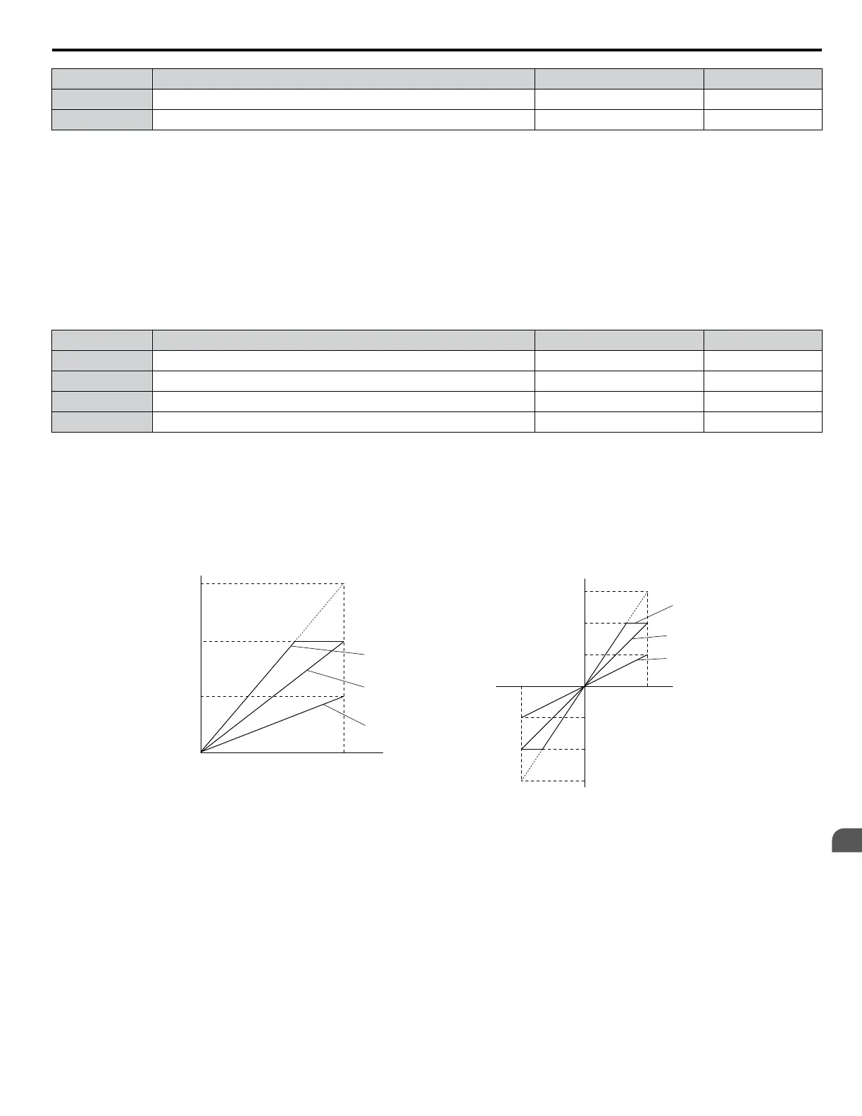
Parameters H4-02 and H4-05 set the terminal FM and AM output signal level when the value of the selected monitor is at
100%. Parameters H4-03 and H4-06 set the terminal FM and AM output signal level when the value of the selected monitor
is at 0%. Both are set as a percentage, where 100% equals 10 Vdc or 20 mA analog output and 0% equals 0 V or 4 mA. The
output voltage of both terminals is limited to +/-10 Vdc.
The output signal range can be selected between 0 to +10 Vdc or -10 to +10 Vdc, or 4 to 20 mA using parameter H4-07 and
H4-08. Figure 1.55 illustrates how gain and bias settings work.
No. Name Setting Range Default
H4-02 Multi-Function Analog Output Terminal FM Gain -999.9 to 999.9% 100.0%
H4-03 Multi-Function Analog Output Terminal FM Bias -999.9 to 999.9% 0.0%
H4-05 Multi-Function Analog Output Terminal AM Gain -999.9 to 999.9% 50.0%
H4-06 Multi-Function Analog Output Terminal AM Bias -999.9 to 999.9% 0.0%
Using Gain and Bias to Adjust Output Signal Level
When viewing a gain setting parameter (H4-02 or H4-05) on the HOA keypad, the analog output will supply a voltage signal
equal to 100% of the monitor value (including changes made from bias and gain settings). When viewing a bias setting
parameter (H4-03 or H4-06), the analog output voltage will supply a signal equal to 0% monitor value.
Example 1: Set H4-02 to 50% for an output signal of 5 V at terminal FM when the monitored value is at 100%.
Example 2: Set H4-02 to 150% for an output signal of 10 V at terminal FM when the monitored value is at 76.7%.
Output Voltage
Output Voltage
0 V
5 V
10 V
Gain 150%
Bias 0%
Gain = 150%
Bias = 0%
Gain = 100%
Bias = 0%
Gain = 50%
Bias = 0%
Gain 100%
Bias 0%
Gain 50%
Bias 0%
100%
Monitor Value
Monitor Value
0%
H4-07, 08 = 0 H4-07, 08 = 1
10 V
-10 V
100%
5 V
15 V
-5 V
-15 V
-100%
Figure 1.55 Analog Output Gain and Bias Setting Example 1 and 2
Example 3: Set H4-03 to 30% for an output signal of 3 V at terminal FM when the monitored value is at 0%.
1.7 H: Terminal Functions
YASKAWA SIEP YAIZ1U 03B YASKAWA AC Drive – Z1000 Programming Manual
97
1
Parameter Details

 Loading...


