4-4 IM 765501-01E
×
1
OUTPUT Lo
OUTPUT Hi
r
2
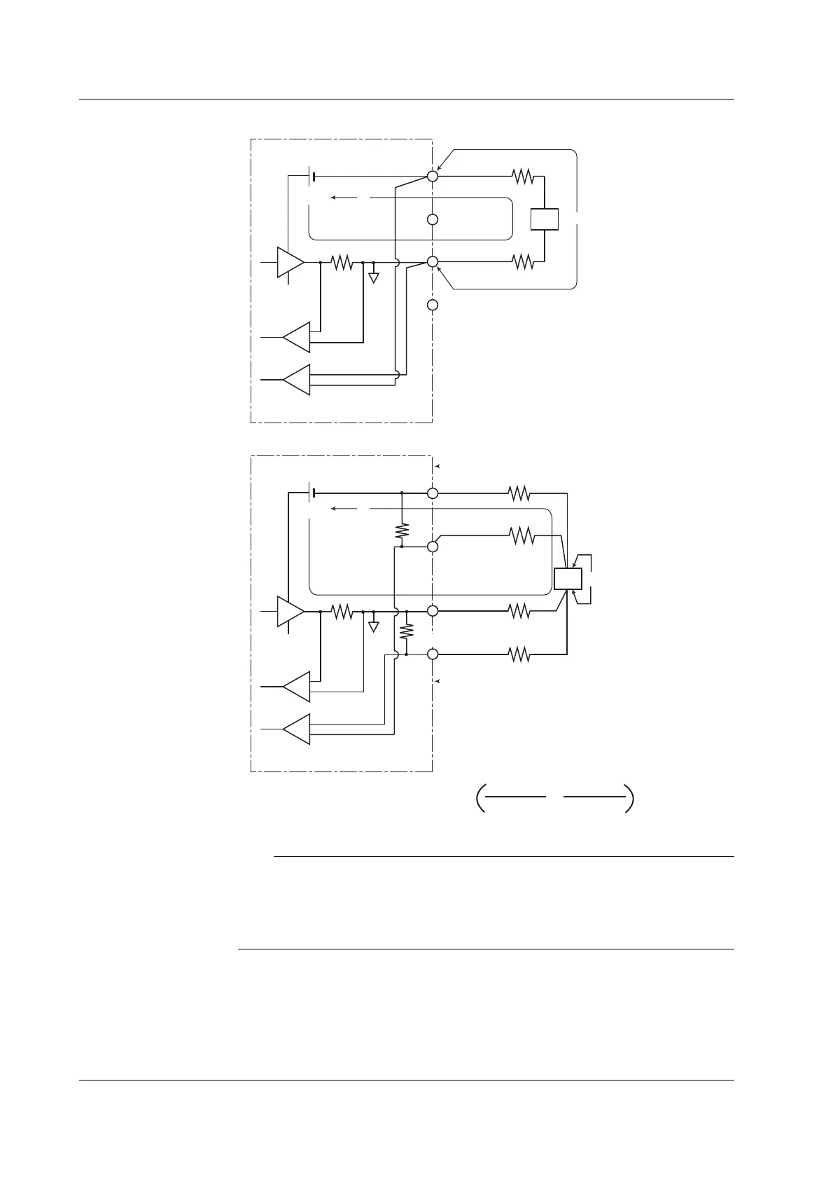
• Two-terminal connection
GS610
DUT
SENSE Lo
SENSE Hi
r
1
Current
sense
Voltage sense
An error equal to Io × (r1 + r2) occurs
DUT: Device Under Test
V
o
I
o
×1
OUTPUT LO
OUTPUT HI
r2
r4
• Four-terminal connection
DUT
SENSE LO
SENSE HI
r1
r3
Current
sense
Voltage sense
Vo
Io
GS610
DUT: Device Under Test
40kΩ
40kΩ+r
3
+r
1
40kΩ
An error approximately equal to Io ×
r
1
• r
3
40kΩ+r
4
+r
2
r
2
• r
4
+
occurs, but the effects are small if r1 to r4 are adequately small.
Note
If 4W (four-terminal connection) is used, the source voltage between the Hi OUTPUT and Lo
OUTPUT terminals is greater than the voltage generated at the load. If the source voltage
between the Hi OUTPUT and Lo OUTPUT terminals exceeds the source range, the GS610
cannot generate the voltage correctly, and abnormal load detection may be activated causing
the output to be turned OFF. Be sure that the source voltage between the Hi OUTPUT and
Lo OUTPUT terminals do not exceed the source range of the range setting.
<<Corresponding Command Mnemonic>>
:SENSe:RSENse
4.2 Connection Type (Remote Sense and Local Sense)
 Loading...


