6-62
IM 701310-01E
• Data
You can use the Data Field value as a trigger condition. Set this value only when the
frame type is set to Data Frame.
• Comparison Condition
The data trigger condition is met when the result of comparing
the input signal Data
Field value with the reference value meets the selected comparison condition.
Don’t care Not used as a trigger condition
True When the input signal value meets the reference value
False When the input signal value does not match the reference value
Greater/Equal When the input signal value is greater than or equal to the reference value
Less/Equal When the input signal value is less than or equal to the reference value
Between When the input signal value is within the reference range that includes the
boundary reference values
Out of Range When the input signal value is outside the reference range that excludes the
boundary reference values
• Data Pattern
Set the data pattern for the length specified by DLC in hexadecimal or binary
no
tation. The data pattern is valid only when the comparison condition is set to True
or False.
• If you specify X, the condition is assumed to be met regardless of the corresponding bit
status.
• If a binary pattern contains any Xs, the corresponding hexadecimal display will be “$.”
• Reference Value Data(Dec)
• If you set the comparison condition to Greater/Equal or Less/Equal, set one
reference value.
• If you select Between or Out of Range, set two reference valu
es to define a
reference range. The values are automatically adjusted so that the lower limit is
less than or equal to the upper limit.
• If the comparison condition is
True or False, the data pattern is used as the
reference value.
• Selectable range
Set the selectable range in decimal notation.
Unsigned 0 to 9E+18
The selectable maximum value is limited by the data length
and bit position that are determined by the DLC and MSB/LSB
settings, respectively.
Signed –9E+18 to 9E+18
The selectable minimum and maximum values are limited by the
data length and bit position that are determined by the DLC and
MSB/LSB settings, respectively.
The value is displayed in exponential notation when it exceeds 7 digits (example:
1234567E+10).
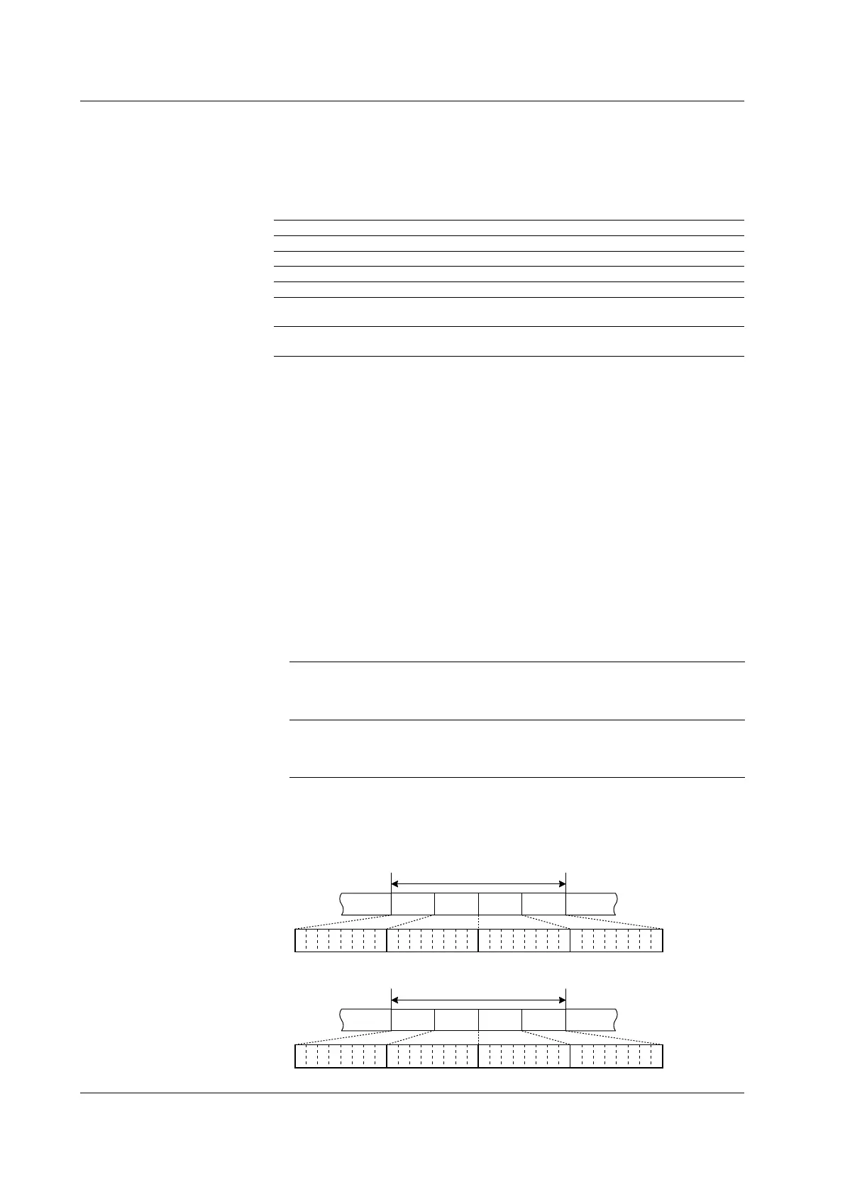
• Byte Order
Set the data byte order to big endian or little endian. For example, the following
figure shows a 4-byte data stream on the bus (12345678 in hexadecimal notation).
Big endian
12 34 56 78
0 0 0 1 0 0 1 0 0 0 1 1 0 1 0 0 0 1 0 1 0 1 1 0 0 1 1 1 1 0 0 0
Bit
0
Bit
31
Bit
0
Bit
31
Data 3Data 2Data 1Data 0
Data Field
Little endian
78 56 34 12
0 1 1 1 1 0 0 0 0 1 0 1 0 1 1 0 0 0 1 1 0 1 0 0 0 0 0 1 0 0 1 0
Data 0Data 1Data 2Data 3
Data Field
6.16 Triggering on a CAN Bus Signal
 Loading...


