2-3
IM 701310-01E
Explanation of Functions
3
2
1
4
5
6
7
8
9
10
11
12
13
14
15
16
17
18
19
App
Index
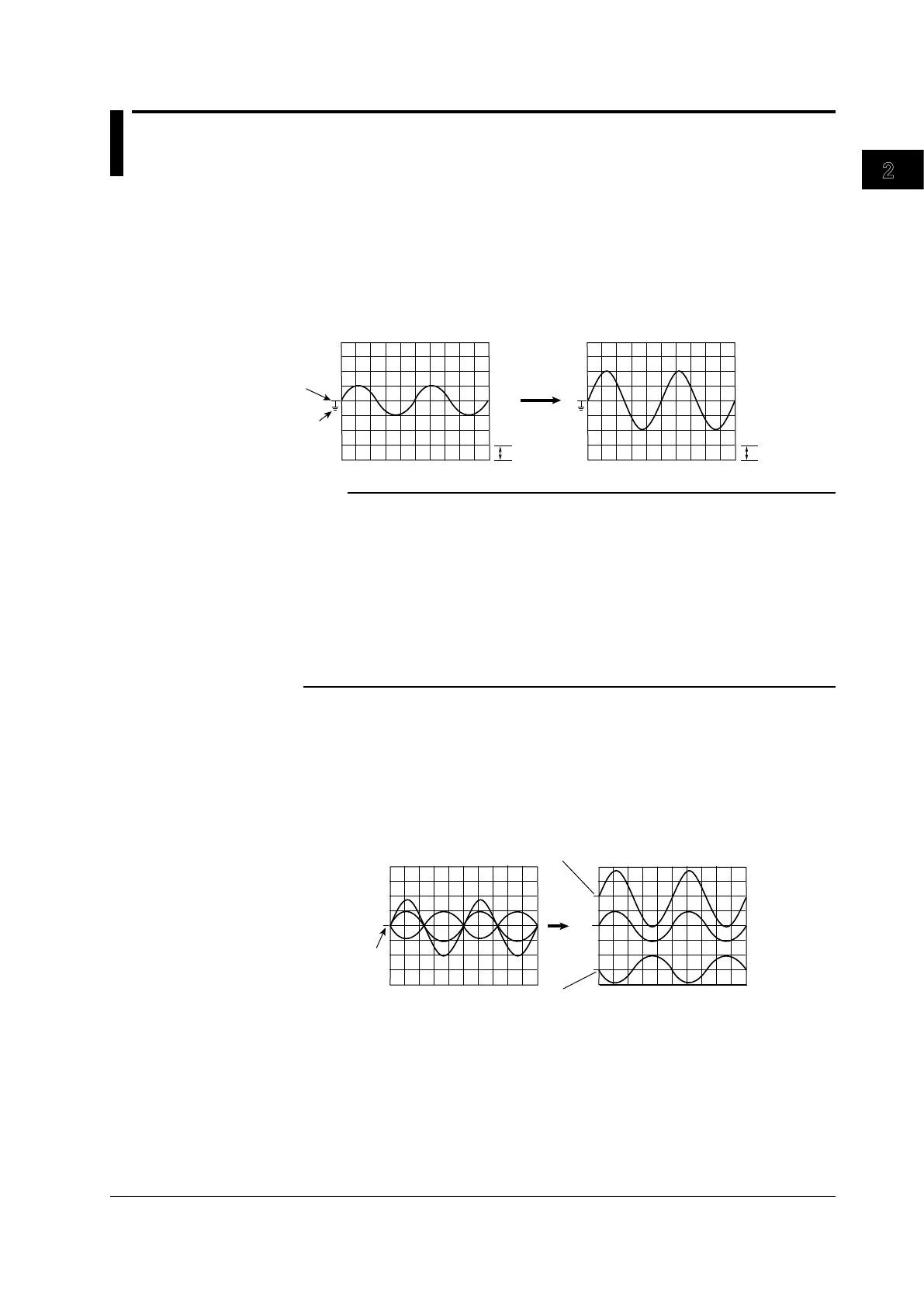
2.3 Vertical and Horizontal Axes
The vertical sensitivity setting is used to adjust the displayed amplitude of the waveform
for easy viewing of the signal. The vertical sensitivity is set by assigning a voltage or a
current value to one grid square (1 division) on the screen.
By switching attenuators with different attenuation and changing the amplification of the
pre-amplifier, the sensitivity changes in steps (for example, voltage sensitivity changes in
steps as in 1 V/div, 2 V/div, and 5 V/div).
1 div = 1.00 V 1 div = 0.500 V
If 1.00 V/div is changed to 0.500 V/div
Vertical position
mark
GND level
mark
Note
Vertical Sensitivity Setting and Measurement Resolution
To measure a voltage with high precision, the vertical sensitivity should be adjusted so that the
input signal is measured with as large an amplitude as possible.
The DL9000 uses 8-bit A/D converters to sample the input signal at a resolution of 250 levels
(LSB). The waveforms are displayed using 25 levels per division.
Valid Data Range
The output with 250 levels as described above is displayed at 25 levels per division, and
therefore the effective display range is �5 divisions from the center of the screen. However, if
the vertical axis position is moved after stopping data (signal) acquisition, the valid data range
also moves by the same amount.
Vertical Position of the Waveform ►For the procedure, see section 5.3
Since the DL9000 can display eight waveform channels, including computation channels,
the waveforms are displayed superimposed, and can be difficult to read.
In this case, you can change the display position of waveforms on the vertical axis (vertical
position) in the range of �4 divisions for easier viewing. The vertical sensitivity switches
around the vertical position (mark).
Position 2.00 div
Position −3.00 div
Position 0.00div
Vertical position
mark
 Loading...


