2-1
IM 701310-01E
Explanation of Functions
3
2
1
4
5
6
7
8
9
10
11
12
13
14
15
16
17
18
19
App
Index
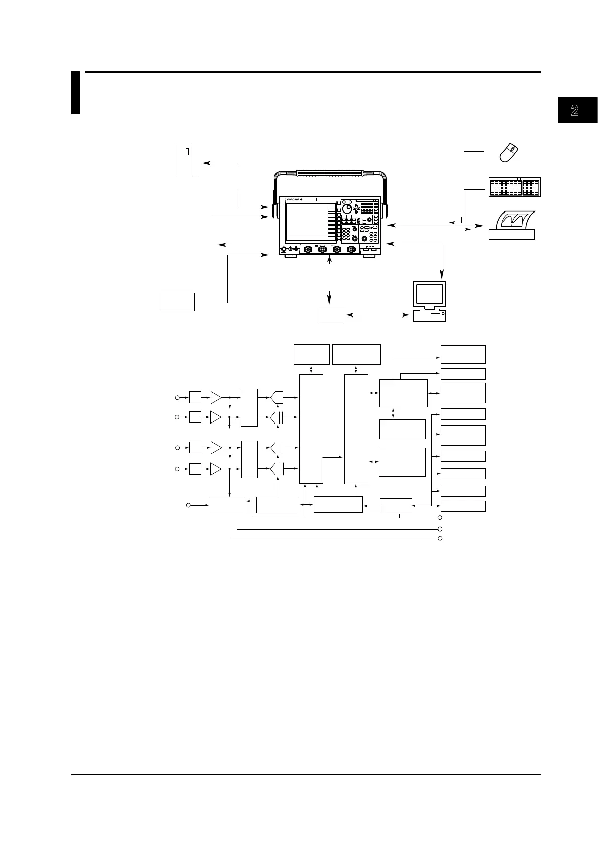
2.1 Block Diagram
System Configuration
ESC
RESET
SET
M
k
m
u
n
p
D E F X
A
B
C
7
8
9
4
5
6
1
2 3
0
BS
CLEAR
EXP
MENU
PRINT
FILE UTILITY
FILE
SYSTEM
SHIFT
SETUP
HELP
HISTORY
CLEAR
HISTORY
ACQ
COUNT/ACTION
ZOOM
DISP 1
DISP 2
ZOOM 1
ZOOM
2
MAG
ACQUIRE/HORIZON TAL
ACQ
START/STOP
SAMPLING/
LENGTH
POSITION/
DELAY
T/DIV
TRIGGER
EDGE/
STATE
ENHANCED
WIDTH
EVENT
INTERVAL
SOURCE
DISPLAY
INTENSITY
ACCUM
CLEAR
FORM
ACCUM
ANALYSIS/
XY
WINDOW 1
WINDOW 2
MEAS URE
CURSOR
TELECOM TEST
PARAM
VERTICAL
CH 1
M 1
CH 2
CH 3
CH 4
M 2
M 3
M 4
POSITION
TRIG'D
TRIG MODE/
HOLD OFF
PUSH
FINE
PUSH
FINE
SCALE
SNAP
CLEAR
SNAP
POWER
COMP
CH 1 CH 2 C H 3 CH 4
1
/20 pF 150
Vrms
CATI 5
Vrms,10 Vpk
LEVEL/
COUPLING
DL9240L
10GS/s
1.5GHz
DIGITAL OSCILLOSCOPE
PC
USB printer
USB keyboard
Built-in printer (optional)
Screen image print
External trigger
input
Video signal (XGA)
GO/NO-GO output
Trigger comparator
output
Screen image data
Input
USB peripheral
device interface
USB interface
Ethernet interface (optional)
USB mouse
Input
External USB
device
USB peripheral
device interface
PC card
Analog signal
input
Waveform data
Setup data
Screen image data
Waveform data / Setup data
Screen image data
Polygon graphing
Waveform data
Setup data
Screen image data
Device under
measurement
Block Diagram
CH1
External
Trigger
Input
ATT
Pre-
AMP
Cross
Point
SW
A/D
Acquisition
Memory
Data
Processing
Memory
CPU
Color LCD
Trigger
Circuit
Time Base
Trigger Output
Trigger Comparator
Output
GO/NO-GO Output
(optional)
CH2
CH3
CH4
Primary
Memory
Display
Memory
Display
Processing
Circuit
Built-in
Printer
PC Card
PC Card
(optional)
Ethernet
Video
Output
USB
Peripheral
USB
Controller
Primary Data
Processing Circuit
Secondary Data
Processing Circuit
Key board
Signal Flow
The signal applied to each signal input terminal is first passed to the vertical control circuit
consisting of an attenuator (ATT) and pre-amplifier. At the attenuator and pre-amplifier, the
amplitude of each input signal is adjusted according to the settings such as the input coupling,
voltage sensitivity (Scale), and offset voltage. The adjusted input signal is then passed to the
cross-point switch. The signal input to the cross-point switch is passed to the A/D converter
according to the interleave setting.
At the A/D converter, the received voltage level is converted into digital values. The digital data
is written to the primary memory by the primary data processing circuit at the sample rate that
matches the time axis setting.
When the trigger is applied, data written to the primary memory is transferred to the acquisition
memory.
The data written to the acquisition memory is converted into waveform display data by the
secondary data processing circuit, transferred to the waveform processing circuit, and stored
in the display memory. The waveforms are displayed on the LCD using the data stored in the
display memory.
Chapter 2 Explanation of Functions
 Loading...


