2-5
IM 701310-01E
Explanation of Functions
3
2
1
4
5
6
7
8
9
10
11
12
13
14
15
16
17
18
19
App
Index
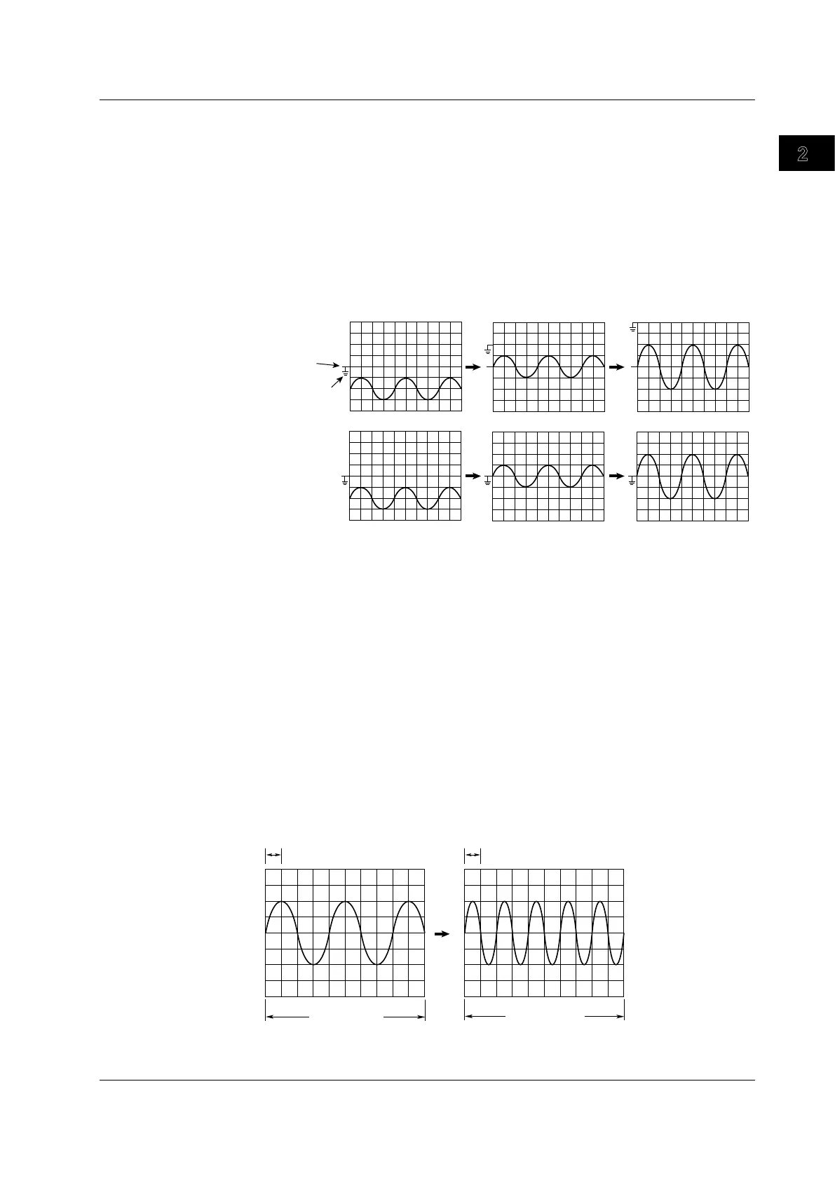
Offset Voltage ►For the procedure, see section 5.2
To observe a signal riding on top of a predetermined voltage, an offset voltage can be
applied to subtract the predetermined voltage so that only the changes in the signal can
be observed with higher vertical sensitivity.
Usually, the offset voltage does not affect the cursor measurement values, the result
of the automated measurement of waveform parameters, or the computed values.
However, by setting Offset Cancel to ON (see section 5.10), you can calculate with the
offset voltage subtracted from cursor measurement values, results of the automated
measurement of waveform parameters, and computed values.
1.00 V/div
Offset 0.00 V
Position 0.00 div
1.00 V/div
Offset –2.00 V
Position 0.00 div
0.500 V/div
Offset –2.00 V
Position 0.00 div
When Offset Cancel
is OFF
When Offset Cancel
is ON
Vertical position
mark
GND level mark
Inverted Waveform Display
This inverts the waveform display about the Position value as center. The inversion
applies to the display only, and does not affect the measurement value. Setting the
inverted display ON/OFF does not affect waveform parameter automatic measurement
values or calculations.
Bandwidth Limit ►For the procedure, see section 5.5
You can set a upper bandwidth limit on the input signal for each channel. You can
observe signals with the noise components above the specified frequency eliminated.
The frequency can be selected from FULL, 200 MHz, 20 MHz, 8 MHz, 4 MHz, 2 MHz, 1
MHz, 500 kHz, 250 kHz, 125 kHz, 62.5 kHz, 32 kHz, 16 kHz, and 8 kHz.
Horizontal Axis (Time Axis)
Time Axis Setting ►For the procedure, see section 5.8
The time axis scale (T/div) is set as time per grid square (1 div). The setting range is from
500ps/div to 50s/div. Since horizontal axis display range is 10 div, the waveform display
time is T/div
×
10.
1 div = 500 µs
10 div = 5 ms
1 div = 1 ms
10 div = 10 ms
2.3 Vertical and Horizontal Axes
 Loading...


