Installation and Communication 3 - 9
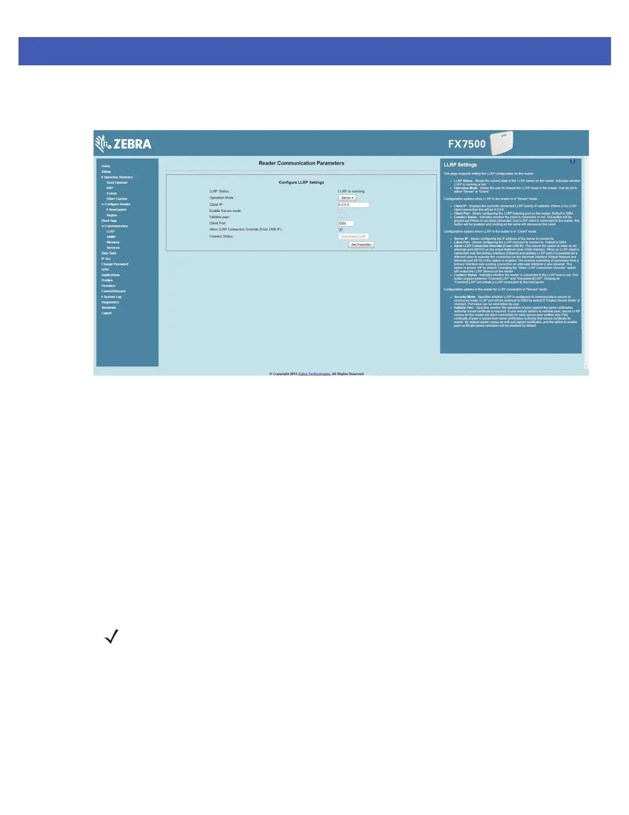
4. The FX7500 listens on the USB virtual interface on a fixed port (49152) as well as on the standard LLRP
port (5084). To enable this, select the
Allow LLRP Connection Override check box in Configure LLRP
Settings
console window.
Figure 3-5
Communication / Configure LLRP Settings Window
Only one LLRP session can be active on the reader, either through the primary Ethernet interface or through
the virtual network over USB interface.
If a connection is active on one interface, a subsequent connection attempt on a second interface disconnects
the first. The second connection attempt always prevails and creates a new session.
GPIO Interface Connection
This pluggable terminal block type allows connecting individual wires independently. A single connector
accommodates both inputs and outputs. See Table A-5 on page A-6 for pinout information.
GPIO signals allow some flexibility. Inputs are pulled up within the reader to +5 VDC and can be shorted to
ground to pull them low. This allows driving them directly via simple relay or switch contacts. Alternatively, 5V
logic can drive inputs. In the logic low state, the current sourced from the reader is approximately 3 mA, so
standard gates in most logic families can drive them. Current flow in the high state is negligible. When the
equipment uses an external +24 VDC power supply, a +24 VDC connection is provided. This output is not
available when an external 24 VDC supply is not present.
The general purpose outputs are open-drain drivers, pulled up to 5V. Each output can withstand voltages up to
+30 VDC but should not be driven negative. For best results use the +24 VDC supply as a source of external
current and use the outputs directly to drive 24V relays, indicator lamps, etc., wired between the 24V supply
and individual general purpose outputs. Although each output can sink up to 1A, the maximum current that can
be drawn from the internal 24V supply is 1A, so use an external power supply if the current requirement
exceeds this. Note that the state of the general purpose outputs is inverted, e.g., driving a GPO line high at the
processor pulls the corresponding output low.
NOTE Do not connect the +24 VDC output directly to either general purpose input that tolerates voltages in
excess of 5V but is designed to operate optimally within the range of 0 to +5 VDC.