APPENDIX C RF AIR LINK CONFIGURATION
Introduction
This appendix lists the different air link configurations supported. The air link configuration is available through
LLRP and RFID3 API interfaces.
Radio Modes
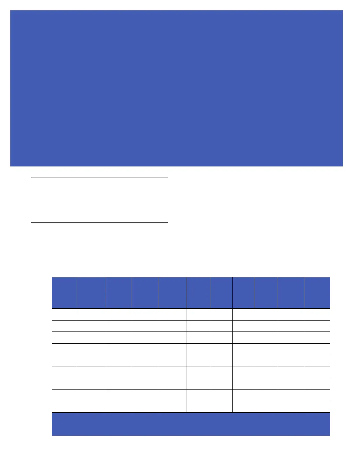
The supported modes are exposed as a list of individual UHFC1G2RfModeTableEntry parameters in regulatory
capabilities as shown in Table C-1 and Table C-2. The Mode Index column refers to the index used to walk the
C1G2UHFRFModeTable. Refer to the EPCglobal Low Level Reader Protocol (LLRP) Standard.
Table C-1
Radio Modes for FCC Readers
RF Mode
Index
Divide
Ratio
BDR
Value
M Value
M2=2,
FM0=1,
M4=4,
M8=8
FLM
Value
PIE
Value
Min
Tari
Max
Tari
Step
Tari
Spectral
Mask
Indica-
tor**
EPC HAG
T&C
Conform-
ance
1 64/3 640000 1 PR_ASK 1500 6250 6250 0 Dense false
2 64/3 640000 1 PR_ASK 2000 6250 6250 0 Dense false
3 64/3 120000 2 PR_ASK 1500 25000 25000 0 Dense false
4 64/3 120000 2 PR_ASK 1500 12500 23000 2100 Dense false
5 64/3 120000 2 PR_ASK 2000 25000 25000 0 Dense false
6 64/3 120000 2 PR_ASK 2000 12500 23000 2100 Dense false
7 64/3 128000 2 PR_ASK 1500 25000 25000 0 Dense false
8 64/3 128000 2 PR_ASK 1500 12500 23000 2100 Dense false
9 64/3 128000 2 PR_ASK 2000 25000 25000 0 Dense false
*RF Mode 23 is the automac air link profile which is also the default.
**Spectral mask indicator may vary for certain Tari values. Detailed information is available upon
request.