Control macros 43
Tightening torque: 0.5 N·m (0.4 lbf·ft).
Terminals DGND, AGND and SGND are internally connected to same reference
potential.
1)
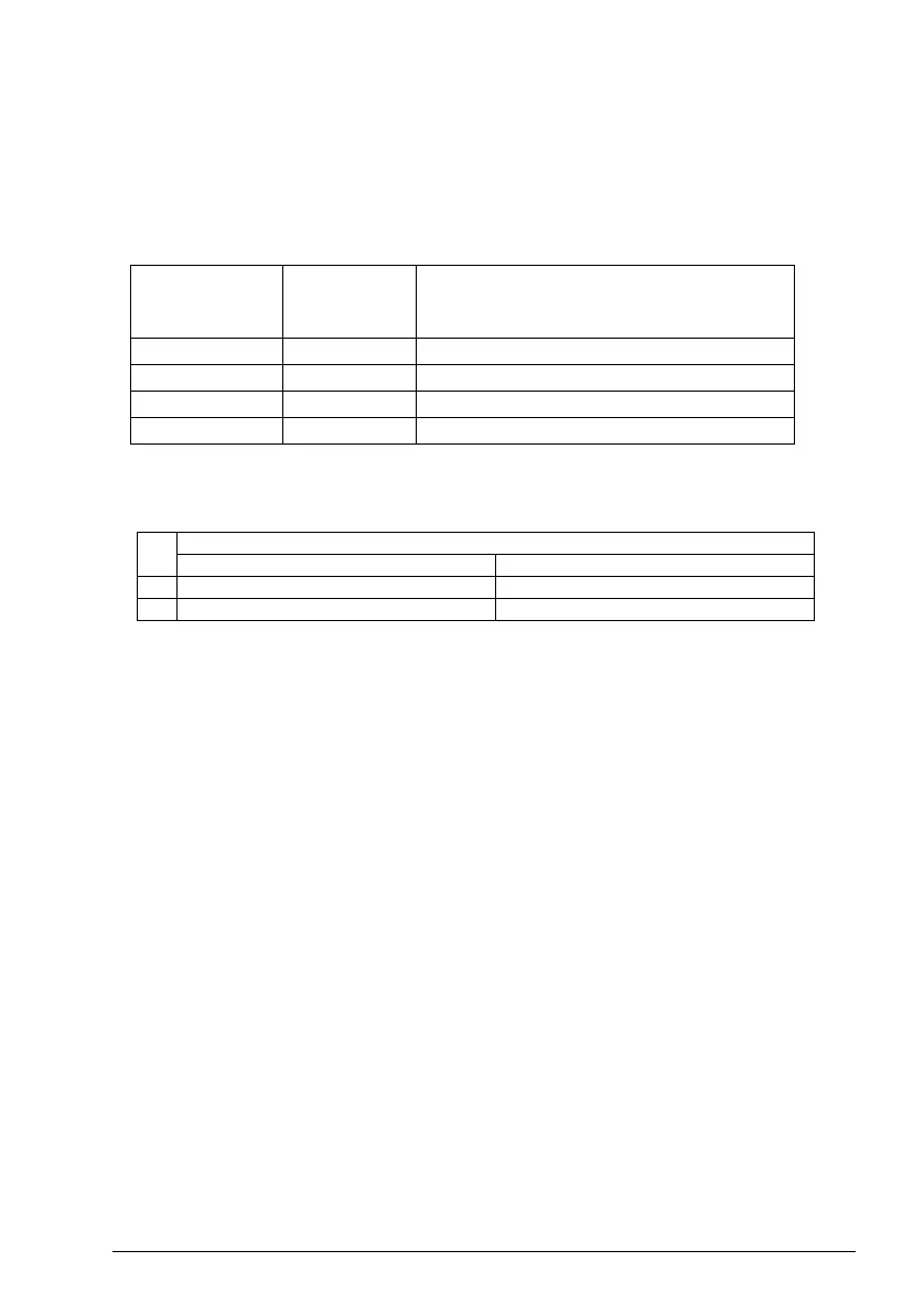
See parameters 40.19 Set 1 internal setpoint sel1 and 40.20 Set 1 internal setpoint
sel2 source table.
2)
Select the correct control mode from the Motor data view or with parameter 99.04
Motor control mode.
3)
PID: 0...10 V -> 0...100% PID setpoint.
4)
The signal source is powered externally. See the manufacturer’s instructions. To
use sensors supplied by the drive aux. voltage output, see connection examples of
two-wire and three-wire sensors in the hardware manual of the drive.
5)
Ground the outer shield of the cable 360 degrees under the grounding clamp on
the grounding shelf for the control cables.
Input signals
•External PID ref (AI1)
• Actual feedback from PID (AI2)
• Start/Stop selection (DI1)
• Constant setpoint 1 (DI2)
• Constant setpoint 2 (DI3)
• Speed/freq selection (DI4)
• Ramp pair selection (DIO1)
Output signals
• Output frequency (AO)
• No Fault [Fault (-1)]
Source defined
by par. 40.19
DI2
Source defined
by par. 40.20
DI3
Internal setpoint active
00
Setpoint source: AI1 (par. 40.16)
10
1 (par. 40.21)
01
2 (par. 40.22)
11
3 (par.40.23)
DI4 Operation/Parameter
Scalar control (default) Vector control
0 Set frequency through AI1 Set speed through AI1
1 28.26 Constant frequency 1 22.26 Constant speed 1

 Loading...


