122 AO2000 CONTINUOUS GAS ANALYZERS | OI/AO2000-EN REV. B
Power supply line connection to an analyzer module
NOTES
The following information and instructions should be followed when con-
necting the 24-VDC power supply to an analyzer module that is not installed
in the central unit but in a separate system housing.
The notes on the power supply (see page 42) must also be considered.
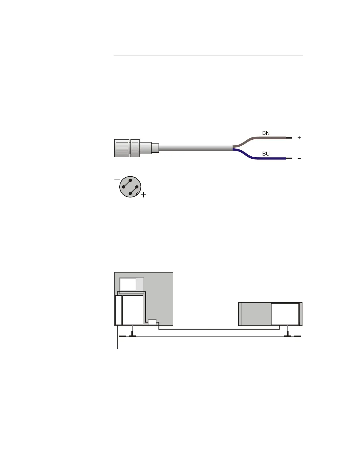
24-VDC connecting cable
If an analyzer module is not installed in the central unit but in a separate
system housing a 24-VDC connecting cable (length 5 m (16.4 feet), cross
section 2 x 0,5 mm
2
) will be supplied.
The receptacle on one cable end is designed to connect to the 24-VDC male
plug on the analyzer module.
1
4
2
3
The illustration shows the pin side of the analyzer module plug and thus the
solder side of the matching female jack.
The wires on the free end of the connecting cable are intended for connec-
tion to
• the power supply filter -Z01 in the central unit or
• an external power supply.
Connecting 24-VDC power from the central unit power supply to a separate
analyzer module
115 / 230 V AC
-Z01
24 V DC
(0,5 mm , 5 m)
2
<
BUS
AM
P
S
CU
EM
AM Analyzer module
CU Central unit
EM Electronics module
PS Power supply
-Z01 Power line filter
BUS System bus
 Loading...


