30 AO2000 CONTINUOUS GAS ANALYZERS | OI/AO2000-EN REV. B
Caldos25, Caldos27, Magnos206: Version for the 'Safety Concept'
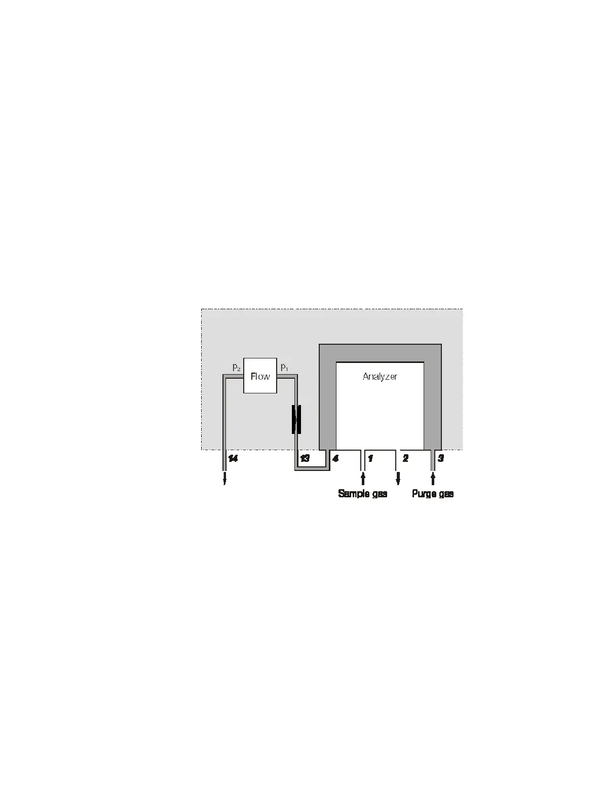
Purging of the thermostat chamber
The thermostat chamber that encloses the analyzer is flushed with purge
gas at a slight positive pressure. The purge curtain formed in this manner
comprises all of the parts of the sample gas path. In the event of a leak in the
sample gas path, the purge gas flows into the analyzer and, in this way, pre-
vents flammable gases from emerging from the analyzer module.
The purge gas is introduced at a flow rate of 15 to 20 l/h and a positive
pressure of p
e
≤ 50 hPa to the thermostat chamber. As a result of the capil-
lary, a positive pressure of p
e
= 7 to 20 hPa is established. The purge gas flow
is measured by a flow meter located downstream from a capillary in the
sample gas path. The outlet pressure should be open to atmospheric pres-
sure.
The signal from the flow sensor is monitored and evaluated by a function
block application (see section "Monitoring of purge gas flow" (see page 32)).
Purge curtain
1
Sample gas inlet
2
Sample gas outlet
3
Purge gas inlet thermostat chamber "Analyzer Purge In"
4
Purge gas outlet thermostat chamber, ex works tubed with 13
13
Purge gas inlet flow monitoring
14
Purge gas outlet flow monitoring "Analyzer Purge Out"
 Loading...


