InformationAction
Art. no. is specified in Required equip-
ment on page 272.
xx1100000688
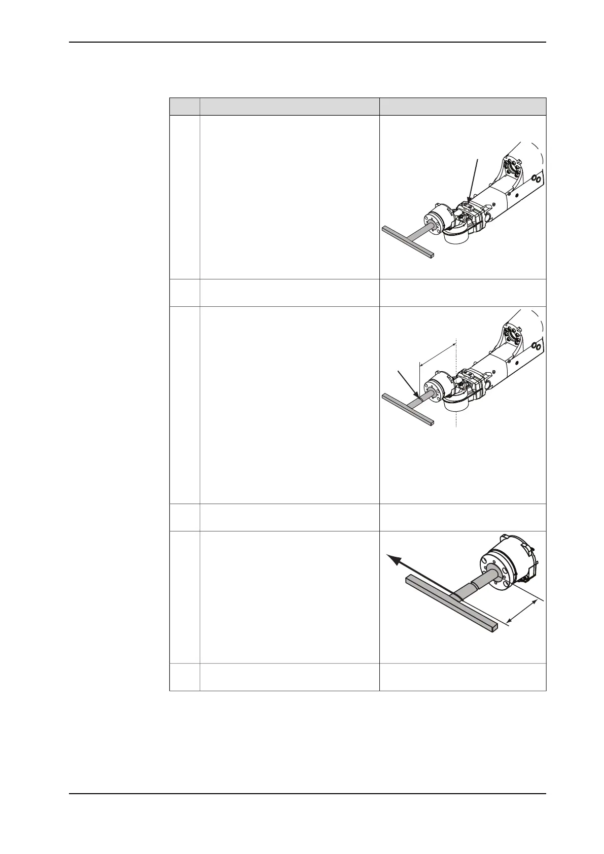
Fit the measuring bracket to the wrist. Use
the holes that are pointed out in the figure.
5
Fit the magnetic foot of the dial indicator
on the measuring bracket.
6
xx1100000689
Place the tip of the dial indicator on the
milled surface of the measuring tool shaft.
7
Distance from the center line of axis 5.
IRB 2600ID - 15/1.85:
A 235 mm
IRB 2600ID - 8/2.00:
A 300 mm
Verify that axis 5 is put in calibration posi-
tion.
8
xx1100000691
A 140 mm
Apply load F=30N with a dynamometer at
the distance A from the turning disk.
9
Remove the load and set the dial indicator
to zero.
10
Continues on next page
Product manual - IRB 2600 273
3HAC035504-001 Revision: Q
© Copyright 2009-2018 ABB. All rights reserved.
4 Repair
4.4.6 Measuring the play, axis 5 (ID upper arm)
Continued

 Loading...


