NoteAction
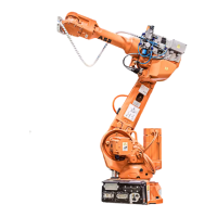
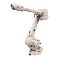
The figure shows IRB 2600 Standard.
xx0900000372
Only applicable to motors axes 3, 4, 5 and 6
on IRB 2600 Standard and axes 3 and 4 on
IRB 2600ID!
Remove the bracket to reach the attachment
screws of the motors.
11
Parts:
• A: Attachment screws, M6x16
quality 8.8-A2F (2 pcs)
• B: Bracket
• C: Clamp
• D: Cable straps
• E: Connection bracket
• F: Connection bracket
• G: Hexagon nut, M5 quality
steel 8-A2F
Connectors:
• Axis-1 motor: R2.MP1
• Axis-2 motor: R2.MP2
• Axis-3 motor: R2.MP3
• Axis-4 motor: R2.MP4
• Axis-5 motor: R2.MP5
• Axis-6 motor: R2.MP6
Connect to pins:
In order to release the brakes of the motor to
be removed, connect the 24 VDC power supply
to the motor.
Only applicable to motors axes 2 and 3!
Release the brake of axis 2 untill the lower arm
firmly rests on the damper.
12
Axes 1, 2 and 3:
• + : pin 2
• -: pin 5
Axes 4 and 5:
• + : pin 4
• - : pin 6
Axis 6 IRB 2600:
• + : pin 4
• - : pin 6
Axis 6 IRB 2600ID:
• + : pin 7
• -: pin 8
CAUTION
The connections for the motor brakes
(24 VDC connection) are phase de-
pendent. If the connection on the pins
is switched, it can cause severe dam-
age to vital parts.
Continues on next page
Product manual - IRB 2600 311
3HAC035504-001 Revision: Q
© Copyright 2009-2018 ABB. All rights reserved.
4 Repair
4.7.1 Removing motors
Continued
 Loading...
