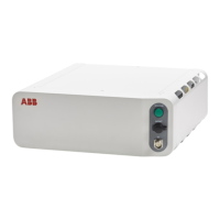
3.7.3 Installing the Ethernet extension switch
Location
The illustration shows the location of the Ethernet extension switch in the controller.
X14 X15
MS
AS1/GS1
AS2/GS2
ES1
ES2
ESOUT1
ESOUT2
MON
AC
PS
PC
HMI
EP
I/O
X0
Q0
X4
X2
X3
X1
PC PWR
PC HDD
ABB Ability™
ETHERNET SWITCH
X18
WAN LAN MGMT
X19
X20
PC STAT
xx1800000029
Required spare parts
Note
The spare part numbers that are listed in the table can be out of date. See the
latest spare parts of the OmniCore C30 via myABB Business Portal,
www.abb.com/myABB.
NoteArticle numberSpare part
3HAC065126-001Ethernet Extension unit slot cover
3HAC059187-001Ethernet Extension switch [3014-
1]
Required tools and equipment
NoteArticle numberEquipment
Content is defined in section
Standard toolkit for controller on
page 570.
-Standard toolkit
-ESD protective wrist band
Required documents
NoteArticle numberDocument
3HAC059896-009,
3HAC063898-009,
3HAC072448-009
Circuit diagram - OmniCore C30,
Circuit diagram - OmniCore C30
for IRB 14050, Circuit dia-
gram - OmniCore C30 for CRB
15000
Continues on next page
Product manual - OmniCore C30 145
3HAC060860-001 Revision: P
© Copyright 2019-2022 ABB. All rights reserved.
3 Installation and commissioning
3.7.3 Installing the Ethernet extension switch

 Loading...