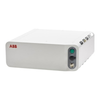
3.7.2 Installing the scalable I/O devices
Location
The location of the base unit used as a scalable I/O internal unit is shown in the
following illustration.
When no base unit is installed, the location for the unit is covered by a slot cover
that must be removed before installation.
X14 X15
MS
AS1/GS1
AS2/GS2
ES1
ES2
ESOUT1
ESOUT2
MON
AC
PS
PC
HMI
EP
I/O
X0
Q0
X4
X2
X3
X1
PC PWR
PC HDD
ABB Ability™
ETHERNET SWITCH
X18
WAN LAN MGMT
X19
X20
PC STAT
xx1800000032
The base unit can also be used as a scalable I/O external unit, with or without
add-on devices.
For more information about installing, configuring, and using the scalable I/O units,
see Application manual - Scalable I/O.
Required parts
NoteArticle numberPart
DSQC10303HAC065147-001DSQC1030 Digital slot cover
3HAC058663-001Scalable I/O Digital base [3032-1]
3HAC060919-001Connectors digital base/add on
Harness K5.1.X5 - Adapter3HAC064092-001Harness Ethernet with Mini-IO
Required tools and equipment
NoteArticle numberEquipment
Content is defined in section
Standard toolkit for controller on
page 570.
-Standard toolkit
-ESD protective wrist band
Required documents
NoteArticle numberDocument
3HAC059896-009,
3HAC063898-009,
3HAC072448-009
Circuit diagram - OmniCore C30,
Circuit diagram - OmniCore C30
for IRB 14050, Circuit dia-
gram - OmniCore C30 for CRB
15000
3HAC070208-001Application manual - Scalable I/O
Continues on next page
Product manual - OmniCore C30 141
3HAC060860-001 Revision: P
© Copyright 2019-2022 ABB. All rights reserved.
3 Installation and commissioning
3.7.2 Installing the scalable I/O devices

 Loading...