This below diagram is used for CRB 15000 controller.
AC input
Power inletP
E
X0 Q0
Power unit
A1
X
1 X6
L,N,PE
L,N,PE
24V TRUNK
X1
X
2
PC
PS
X
13
HMI
MS
AC
L
ED
LED
LED
Main computer
A
2
24V PC
LED
X1
24V HMI
LED
HMI
c
onnection
X4
FlexPendant
24V HMI
Robot
signal
exchange
proxy
K2
xx2100000459
Note
The AC LED shows status of AC input and DC power. It should be lit when the
controller is supplied with power, but will go out 15 minutes after the power is
switched off.
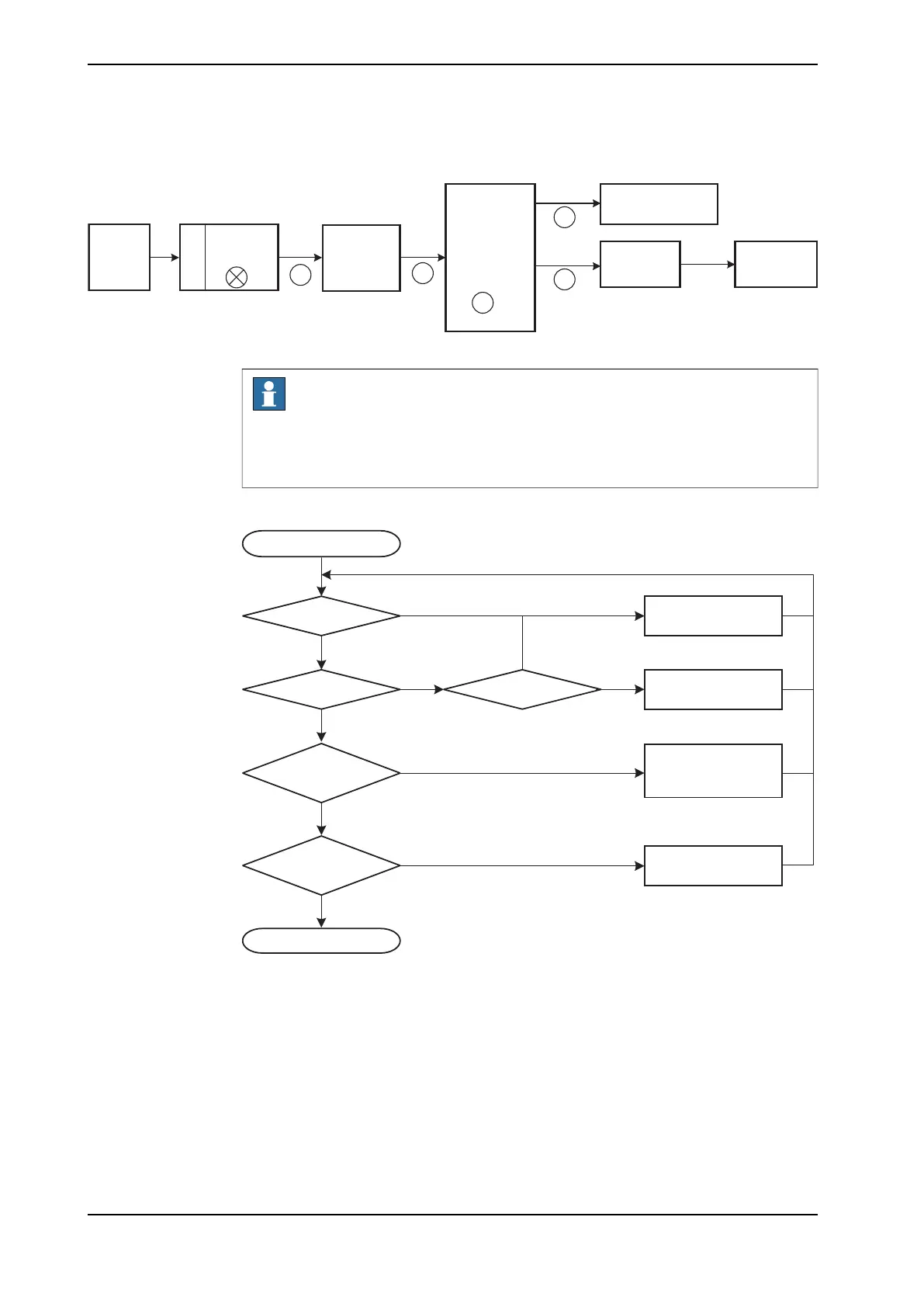
Troubleshooting flowchart
Start-up failure
Check LED PS
Green
Red or flashing
Yes
No
Not lit
Not lit
CRB 15000 controller
Check LED AC
Green
Check LEDs:
MS, PC, HMI
Green
Problem solved
Check LEDs:
PC PWR, PC HDD,
PC STAT
L
it
Troubleshoot power
supply T2
Troubleshoot power
unit A1
Not lit
Troubleshoot robot
signal exchange
proxy K2
Troubleshoot main
c
omputer
xx1800001829
Continues on next page
508 Product manual - OmniCore C30
3HAC060860-001 Revision: P
© Copyright 2019-2022 ABB. All rights reserved.
6 Troubleshooting
6.2.2 Start-up failure
Continued
 Loading...


