The IED point voltage inverses its direction due to presence of series capacitor and its
dimension. It is a common practice to call this phenomenon voltage inversion. Its
consequences on operation of different protections in series compensated networks
depend on their operating principle. The most known effect has voltage inversion on
directional measurement of distance IEDs (see chapter
"Distance protection" for more
details), which must for this reason comprise special measures against this phenomenon.
There will be no voltage inversion phenomena for reverse faults in system with VTs
located on the bus side of series capacitor. The allocation of VTs to the line side does
not eliminate the phenomenon, because it appears again for faults on the bus side of
IED point.
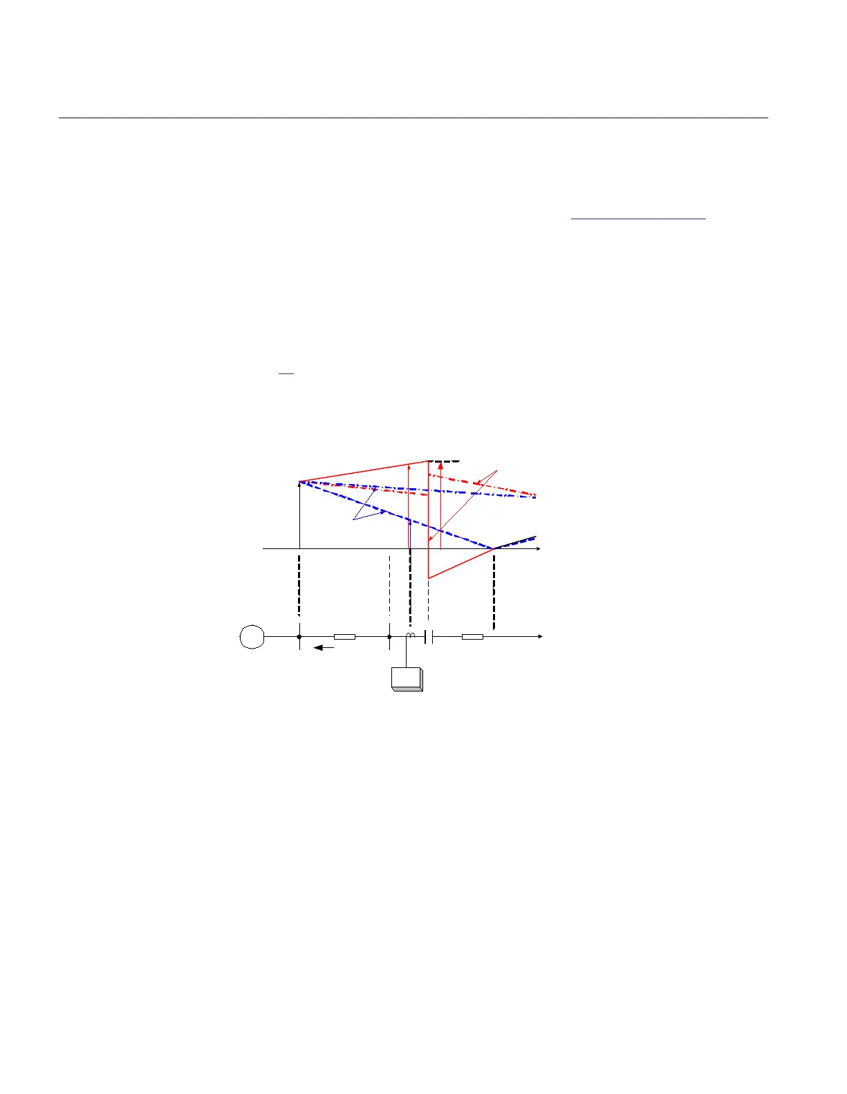
Current inversion
Figure
86 presents part of a series compensated line with corresponding equivalent
voltage source. It is generally anticipated that fault current I
F
flows on non-
compensated lines from power source towards the fault F on the protected line. Series
capacitor may change the situation.
en06000607_ansi.vsd
~
21
XS
X
L1
IF
v
V
M
Source
Fault voltage
Pre -fault voltage
X
C
Source voltage
V’
M
With bypassed
capacitor
With inserted
capacitor
F
X
ANSI06000607 V1 EN
Figure 86: Current inversion on series compensated line
The relative phase position of fault current I
F
compared to the source voltage V
S
depends in general on the character of the resultant reactance between the source and
the fault position. Two possibilities appear:
1
1
0
0
- + >
- + <
S C L
S C L
X X X
X X X
EQUATION1935 V1 EN
(Equation 128)
Section 3 1MRK504116-UUS C
IED application
216
Application manual

 Loading...


