1
A B B
AF AC CF AC CF
A A
I I I
Z Z Z Z Z
I I
æ ö
+
= + × = + + ×
ç ÷
è ø
EQUATION302 V3 EN (Equation 150)
A
B
21
C
I
A
IB
Z
AC
Z
CB
Z
CF
I
A+
I
B
ANSI05000457-2-en.vsd
F
ANSI05000457 V2 EN
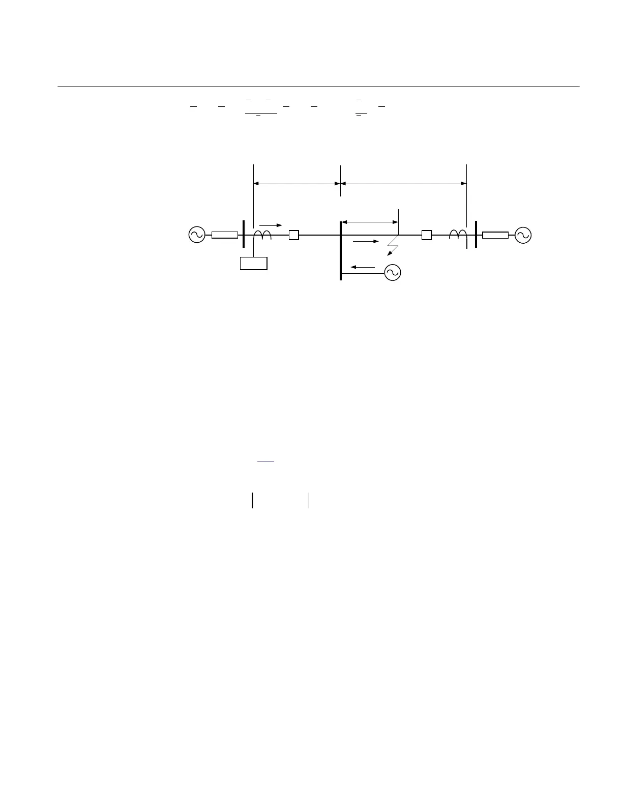
Figure 105:
Setting of reverse zone
The reverse zone is applicable for purposes of scheme communication logic, current
reversal logic, weak-end-infeed logic, and so on. The same applies to the back-up
protection of the bus bar or power transformers. It is necessary to secure, that it always
covers the overreaching zone, used at the remote line IED for the telecommunication
purposes.
Consider the possible enlarging factor that might exist due to fault infeed from adjacent
lines. Equation
151 can be used to calculate the reach in reverse direction when the
zone is used for blocking scheme, weak-end infeed and so on.
EQUATION1525 V4 EN (Equation 151)
Where:
ZL is the protected line impedance
Z2rem is zone2 setting at remote end of protected line.
In some applications it might be necessary to consider the enlarging factor due to fault
current infeed from adjacent lines in the reverse direction to obtain certain sensitivity.
Series compensated and adjacent lines
1MRK504116-UUS C Section 3
IED application
237
Application manual

 Loading...


