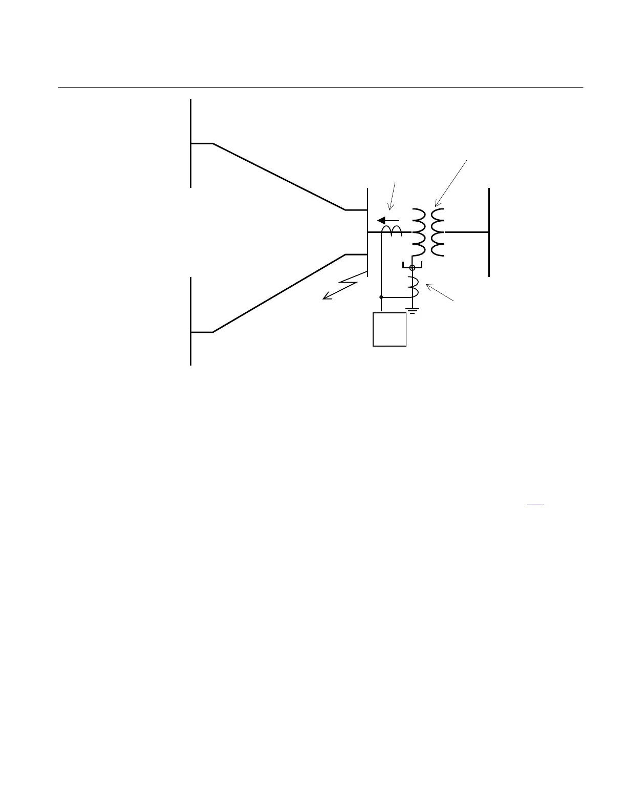
EasyManuals Logo

ABB RET670 Applications Manual

ABB RET670
888 pages
To Next Page IconTo Next Page
To Previous Page IconTo Previous Page
Page #439 background imageLoading...
Page #439 background image
51N
Three phase CT
summated
Single CT
YN/D or YN/Y
transformer
Single phase-
to-ground fault
ANSI05000492_3_en.vsd
0
3I
alt
ANSI05000492 V3 EN
Figure 196: Step 1 fault calculation 1
This calculation gives the current fed to the protection: 3I
0fault1
.
To assure that step 1, selectivity to other ground-fault protections in the network a
short delay is selected. Normally, a delay in the range 0.3 – 0.4 s is appropriate. To
assure selectivity to line faults, tripped after a delay (typically distance protection zone
2) of about 0.5 s the current setting must be set so high so that such faults does not
cause unwanted step 1 trip. Therefore, a fault calculation as shown in figure
197 is made.
1MRK504116-UUS C Section 3
IED application
433
Application manual

Table of Contents

Other manuals for ABB RET670

Questions and Answers:

Question and Answer IconNeed help?

Do you have a question about the ABB RET670 and is the answer not in the manual?

ABB RET670 Specifications

General IconGeneral
Rated Frequency50/60 Hz
InputsAnalog and binary inputs
ApplicationProtection of power systems
Communication ProtocolsIEC 61850, DNP3, Modbus
Operating Temperature Range-25°C to +55°C
MountingRack mounted
Number of Binary InputsUp to 48
Number of Binary Outputs32
Protection FunctionsOvercurrent Protection
OutputsBinary outputs
EnclosureIP 54
TypeLine Differential Protection
Number of Analog Inputs24

Related product manuals