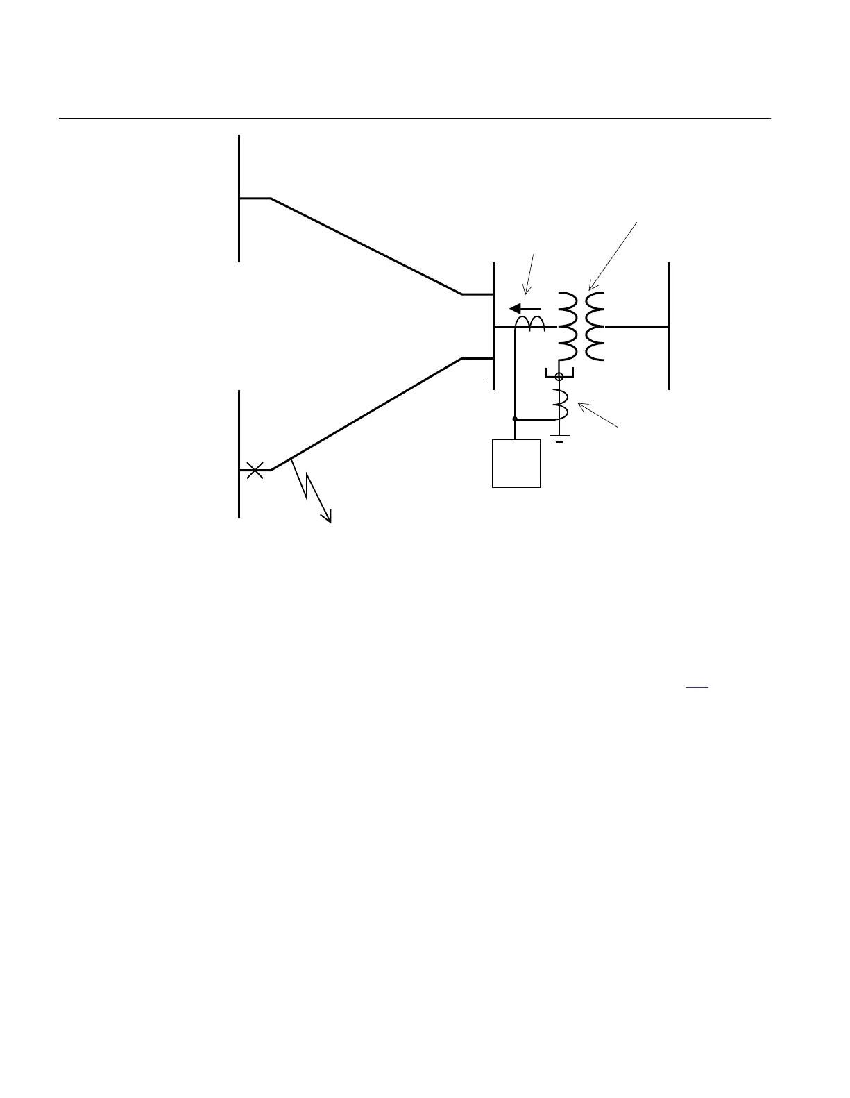
67N
Three phase CT
summated
Single CT
YN/D or YN/Y
transformer
Single phase-
to- ground fault
ANSI05000493_3_en.vsd
0
3I
alt
ANSI05000493 V3 EN
Figure 197: Step 1 fault calculation 1
The fault is located at the borderline between instantaneous and delayed operation of
the line protection, such as Distance protection or line residual overcurrent protection.
This calculation gives the current fed to the protection: 3I
0fault2
The setting of step 1 can be chosen within the interval shown in equation 351.
0fault 2 step1 0fault1
3I lowmar I 3I highmar× < < ×
EQUATION1455 V2 EN
(Equation 351)
Where:
lowmar is a margin to assure selectivity (typical 1.2) and
highmar is a margin to assure fast fault clearance of busbar fault (typical 1.2).
Setting of step 2
The setting of the sensitive step 2 is dependent of the chosen time delay. Often a
relatively long definite time delay or inverse time delay is chosen. The current setting
Section 3 1MRK504116-UUS C
IED application
434
Application manual

 Loading...


