When the overexcitation is equal to the set value of Pickup2, tripping is obtained after
a time equal to the setting of t6. A suitable setting would be Pickup2 = 140% and t6 =
4 s.
The interval between Pickup2 and Pickup1 is automatically divided up in five equal
steps, and the time delays t2 to t5 will be allocated to these values of overexcitation. In
this example, each step will be (140-105) /5 = 7%. The setting of time delays t1 to t6
are listed in table
131.
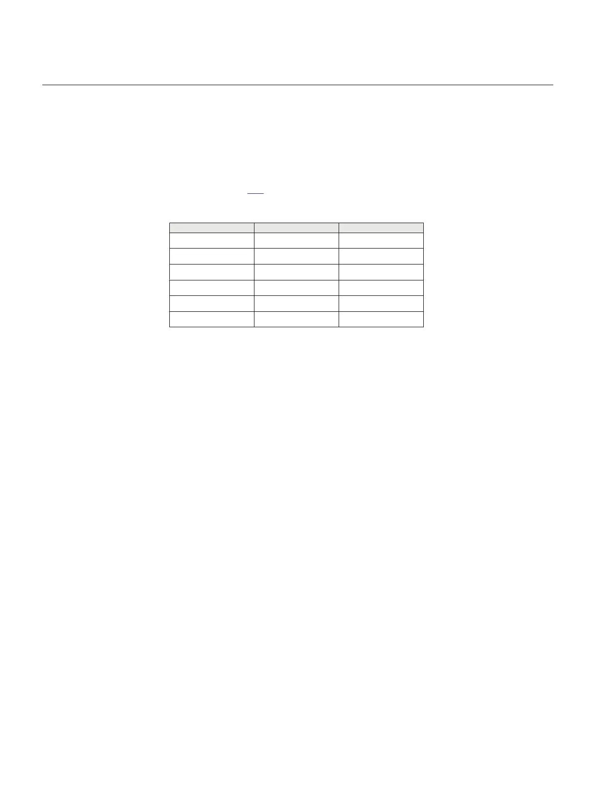
Table 131: Settings
V/f op (%) Timer Time set (s)
105 t1 7200 (max)
112 t2 600
119 t3 60
126 t4 20
133 t5 8
140 t6 4
Information on the cooling time constant T
cool
should be retrieved from the power
transformer manufacturer.
Section 3 1MRK504116-UUS C
IED application
534
Application manual

 Loading...


