Chap. I - Multi-Diag Scope Basic User’s Manual
Scope_manual_en-v110.docx — 20 —
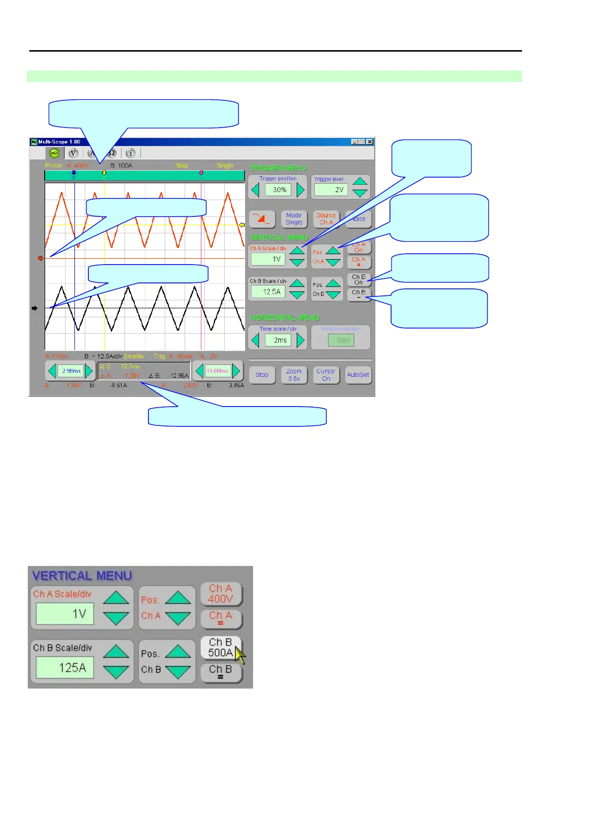
14.2.5 DESCRIPTION OF THE CONTROL AND SETTING OF A (B) CHANNEL PARAMETERS
Fig. 39 – Description of the control and setting of A and B channel parameters (figure applies to version 1.00) - see Fig. 40
Note *) – see Chap. I - 14.7
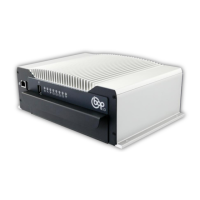
SWITCHOVER OF CONNECTORS ON THE CHANNEL B
The motortester connectors K2, K3, K4 and K5 with attached probes can be connected to the channel “Ch-B“.
By clicking on the “Ch-B“ button, you can gradually switch over between these connectors.
If a correct probe is connected to the connector, the connector will get attached. The description of the attached
probe is displayed on the “Ch-B“ button, e.g. the current probe of 500 A (see the cursor in Fig. 40).
Fig. 40 – View of the “Ch-B“ channel description when the current probe of 500A is connected
Tip for measuring:
If the connector K5 (HV probe) is connected to the “Ch-B“ channel, you can monitor the course of HV voltage
(without any need to connect the synchronization sensor).