Chap. II - Multi-Diag Motortester
Scope_manual_en-v110.docx — 64 —
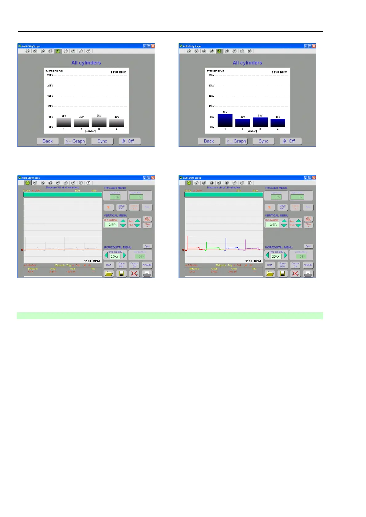
Fig. 145 – Spark voltage bar graph - polarity detected, inversion into
positive done, compression/exhaust phase unknown
Fig. 146 – Spark voltage bar graph - compression/exhaust
phase recognized
Fig. 147 – Oscilloscope display of the HV course after the polarity
detection and its conversion to the positive course and before the
detection of the spark plug ignition time
Fig. 148 – Spark voltage waveform - compression/exhaust
phase recognized
5.4.5 SELECTED CYLINDER MEASUREMENT
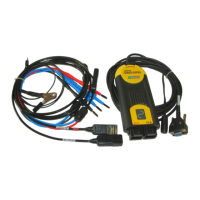
The connection is identical with the connection for the measuring on all cylinders (see Chap. I - 5.4.4), but HV
is displayed for ONE selected cylinder only (see Fig. 149).