2. HELP – SENSOR CONNECTION
This tab allows an easier connection and more intuitive use of measuring sensors and sensors. It is very simple
to use this aid.
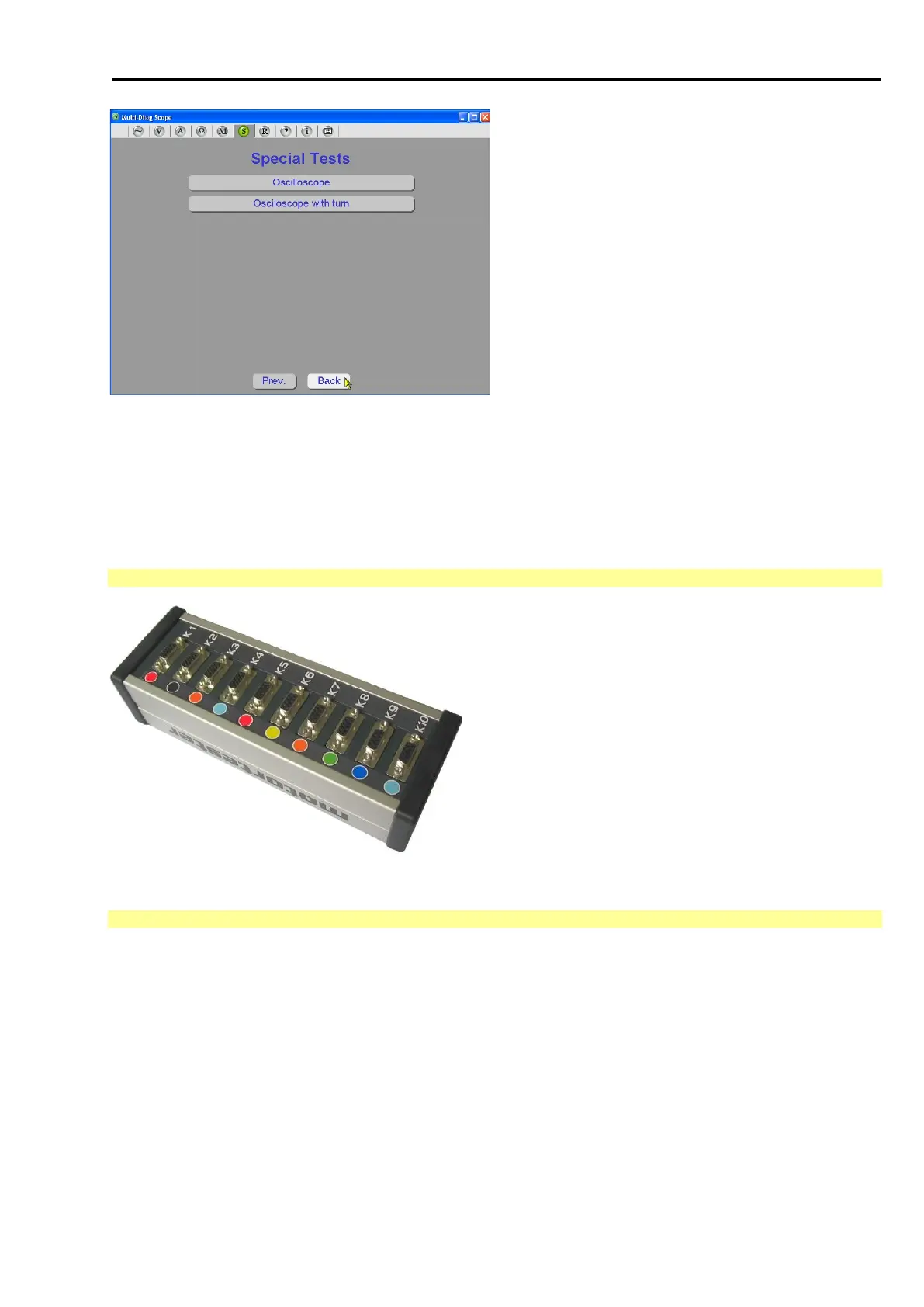
2.1 VIEW OF MOTORTESTER
Fig. 167 – View of motortester and connector with numbers
2.2 MAIN HELP SCREEN
The main screen (see Fig. 168) is divided into a three-column table:
The first column contains the connector indication that exactly (numerically and graphically) corresponds to the
indications on the Motortester (or Multi-Diag Scope).
The second column is regularly updated and informs the users whether the sensor is connected or not. If the
sensor is connected and is in the correct connector (depending on the measurement type), the connector
indication is highlighted in green and the sensor name is written in the second column of the table. If the sensor
is not connected into the correct connector, then it is signalled with red highlighting of the connector indication
and the second column contains the name of the selected sensor, but also the name of the sensor that should
have been connected into the respective connector (in square brackets).
The third column contains the list of all possible measurements. You can click on this list and select individual
measurements. Only those connectors that are relevant for the respective measurement are activated for the