Chap. I - Multi-Diag Scope Basic User’s Manual
Scope_manual_en-v110.docx — 21 —
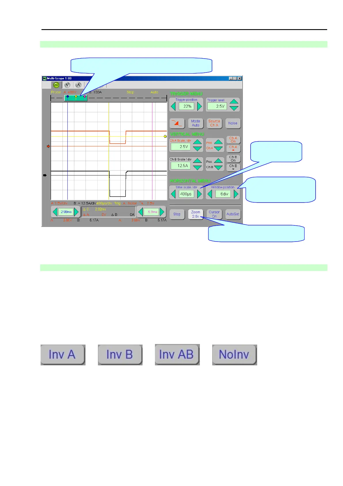
14.2.6 DESCRIPTION OF THE CONTROL AND SETTING OF TIME BASE
Control of the localization
(position) of the displayed part
of the record within the entire
record.
Fig. 41 – Description of the control and setting of time base (figure applies to version 1.00)
14.2.7 DESCRIPTION OF THE INVERT CONTROL FUNCTION
When the invert function is on, the waveform is displayed in an inverted manner.
Activate the inversion of the waveform in channel A (see Fig. 43) by pressing the Inv A button (see the cursor in
Fig. 42).
By pressing this button again (see the cursor in Fig. 43) the waveform of the channel B becomes inverted (see
Fig. 44). By pressing the button once more (see the cursor in Fig. 44) channels A and B become inverted (see
Fig. 45).
By pressing the NoInv button (see the cursor in Fig. 45) the inversion of the waveforms is cancelled (see Fig. 42).
The buttons are programmed in the so-called “Repeat” style:
....... ....... .......