Chap. I - Multi-Diag Scope Basic User’s Manual
Scope_manual_en-v110.docx — 14 —
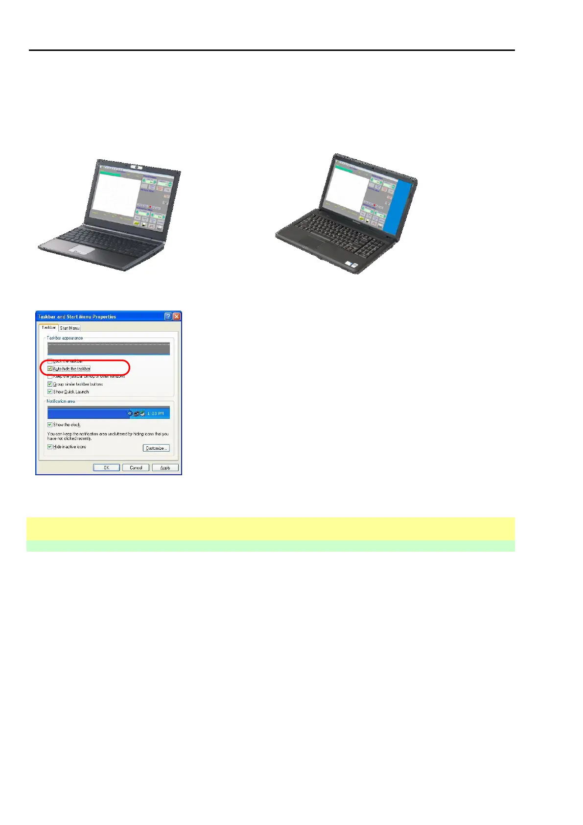
Examples of the oscilloscope's display modes according to the monitor resolution:
800x600 ........... ratio = 0.75 ......... (4:3) ............ see Fig. 30 –
1024x768 ......... ratio = 0.75 ......... (4:3) ............ see Fig. 30 –
1280x1024 ....... ratio = 0.8 ........... (4:3) ............ see Fig. 30 –
1680x1050 ....... ratio = 0.625 ....... (16:9) .......... see Fig. 31 – (monitor will have a stripe on the right
hand side)
Fig. 30 – Oscilloscope display mode on a laptop with a 4:3 screen
Fig. 31 – Oscilloscope display mode on a laptop with a 16:9 screen
Recommendation:
To use maximum possible space for displaying the
oscilloscope, it is recommended to hide the main panel.
Fig. 32 – Activating the main panel hiding function
14.2 OSCILLOSCOPE
14.2.1 BASIC SCREEN
Notice:
The following set of figures describes the independent oscilloscope. The figures were mostly taken
from the Multi-Diag Scope 1.00 version, eventually from 4.0, 5.1, 6.1, 7.3 or 10.1 versions. However
the description is identical for all versions.
For your better orientation, every figure is accompanied with a note in brackets indicating the version
of the given figure. If there is no note, the figure is from the current version.
The description of the oscilloscope connected with a motortester is presented in a separate chapter
about the motortester (Chap. II - Multi-Diag Motortester).