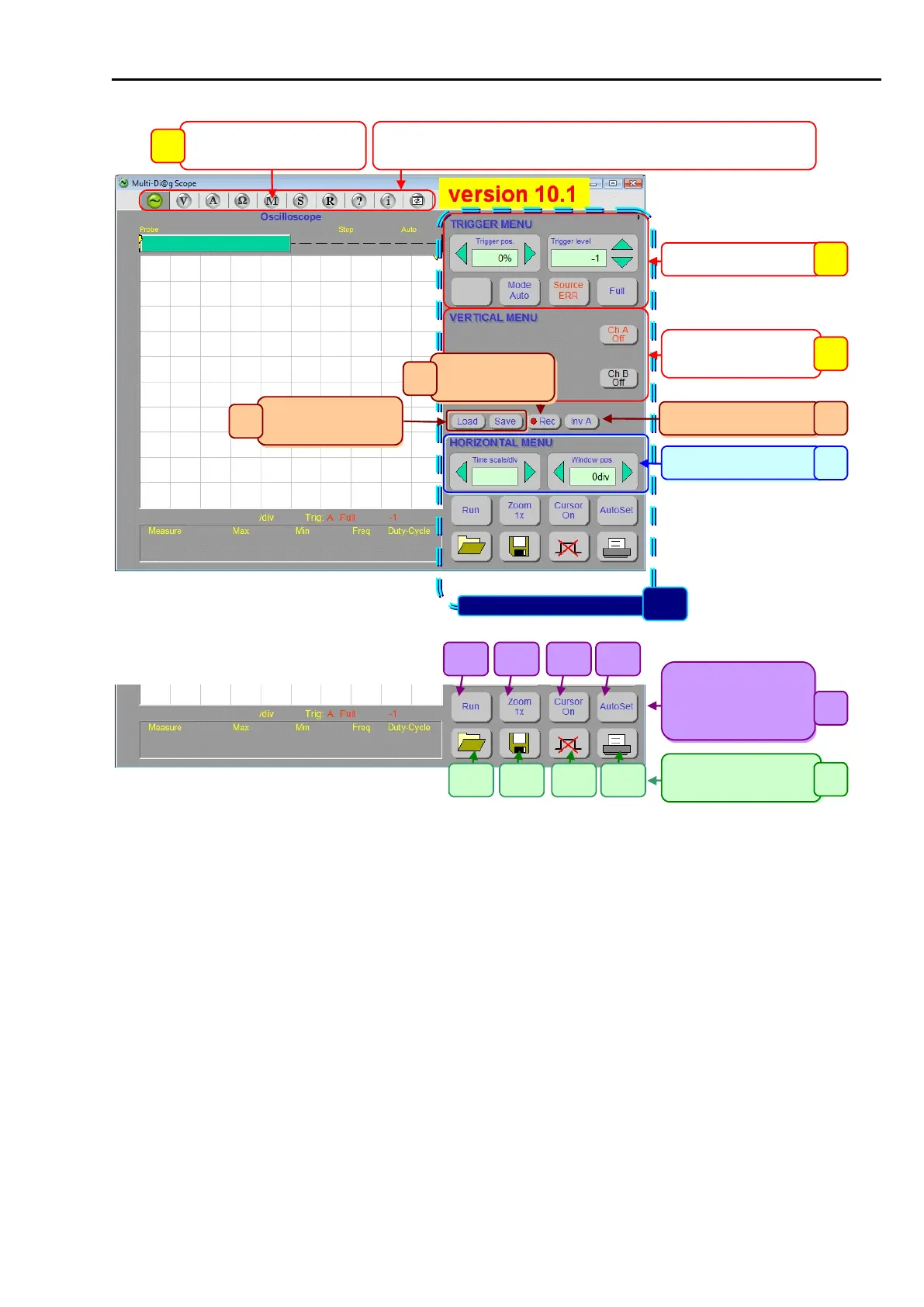
The selection of individual Multi-Diag Scope functional modes. By placing the
mouse cursor on the relevant icon and left-clicking, Multi-Diag Scope gets in the
selected functional mode
Fig. 33 – Multi-Diag Scope window after the program is started (figure applies to version 10.1)
Note to Fig. 33 - Links to the chapters describing the specific function:
1 ............... see Chap. II - Multi-Diag Motortester
2 ............... see Chap. IV - Record Analyzer
3 ............... see Chap. I - 14.2.15
4a ............. see Chap. I - 14.2.12
4b ............. see Chap. I - 14.2.11
4c ............. see Chap. I - 14.2.13
4d ............. see Chap. I - 14.2.14
5 ............... see Chap. I - 14.2.4
6 ............... see Chap. I - 14.2.5
7 ............... see Chap. I - 14.2.7
8 ............... see Chap. I - 14.2.6
9a ............. see Fig. 47, Chap. I - 14.2.17
9b ............. see Fig. 41, Chap. I - 14.2.17
9c ............. see Chap. I - 14.2.8, Chap. IV - 2.3.2
9d ............. see Fig. 47, Chap. I - 14.2.17
10 ............. see Chap. I - 14.2.2