Chap. I - Multi-Diag Scope Basic User’s Manual
Scope_manual_en-v110.docx — 38 —
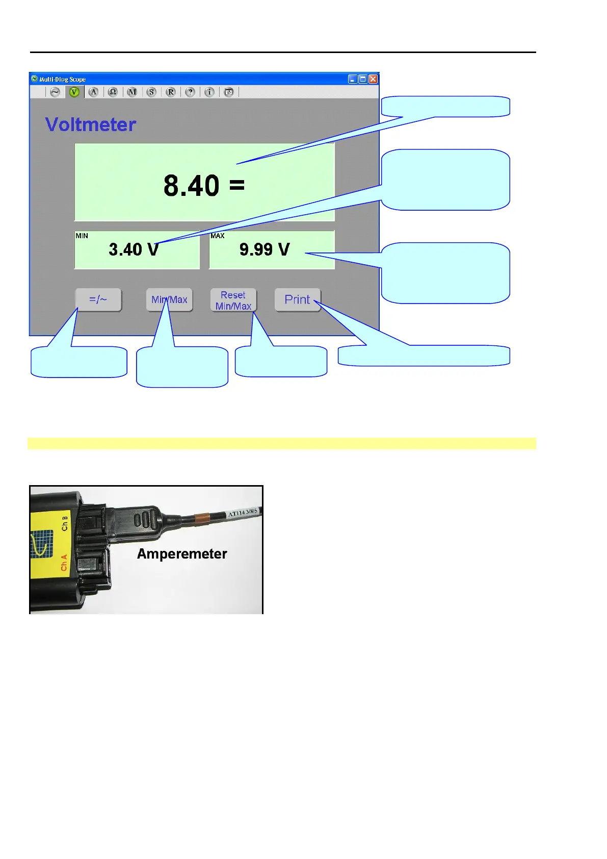
Measured voltage
instantaneous value.
Minimum value of voltage of all
instantaneous voltage values
from the measurement start (i.e.
after the voltmeter is switched on
or after the reset by the RESET
MIN/MAX button).
Maximum value of voltage of all
instantaneous voltage values
from the measurement start (i.e.
after the voltmeter is switched on
or after the reset by the RESET
MIN/MAX button).
Resetting of displayed
MIN and MAX voltage
values.
Switching on/off of the
visualization of MIN
and MAX voltage
values.
Switching between D/C
and A/C voltage
measurement.
Adding a request to the printer queue. For
details refer to the chapter Printer queue.
Fig. 89 – Multi-Diag Scope in the Voltmeter mode with the visualization of the minimum and maximum values of measured voltage (figure
applies to version 7.2.4)
14.4 AMPEREMETER
The current probe plugged into connector Ch-B is required for the measurement (see Fig. 90)
Fig. 90 – Current probe connected for amperemeter measurement
Notes:
a) Oscilloscope cable can be connected to both Channel A and Channel B for oscilloscope measurement
b) No probe on channel warning message is displayed if oscilloscope probe is not properly connected
(see Fig.91)
c) Bad probe on channel warning message is displayed if other probe is connected (see Fig. 92)