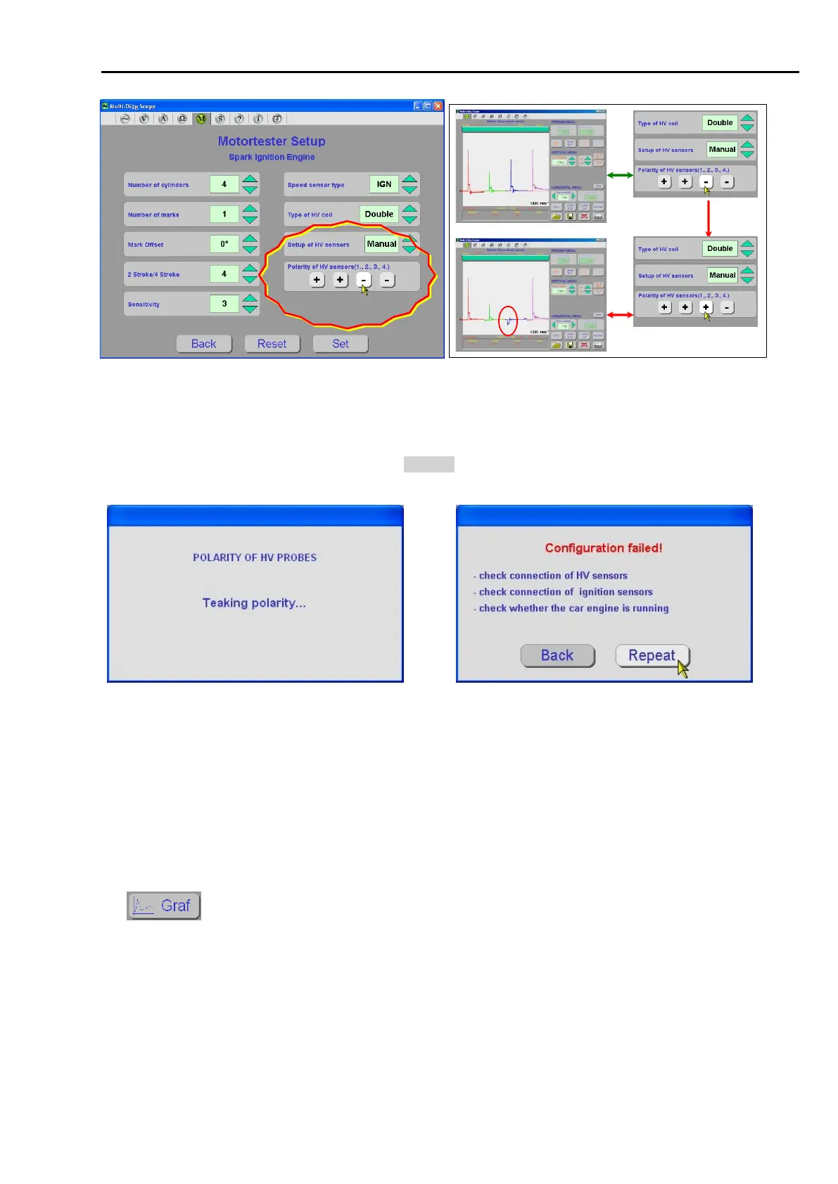
Fig. 142 – After selecting Type of HV coil (Double) a more detailed menu appears. Demonstration of a wrong correction.
The polarity of the third (blue) course was selected incorrectly, because the course appears in the negative level.
B. AUTO MODE
Selecting this mode (see Chap. I - 7, Fig. 117 and Fig. 161) allows automatic switching of spark voltage waveforms
into positive polarity after analyzing the waveform (see Fig. 143).
The waveform analysis can last up to tens of seconds. In case of polarity test failure the message (Fig. 144) is
displayed. After the cause of the problem is removed the action can be repeated or the manual mode can be
selected (see Chap. I - 5.4.4.3A)
If the waveform polarity can be reliably detected the negative portions of signal are inverted into positive values
and the results are presented in the form of bar graph.
Until the device distinguishes between compression and exhaust phase spark, the graph is in grey (Fig. 145).
After doing so, the graph is blue (Fig. 146).
The button switches the display into the oscilloscope mode (Fig. 147 and Fig. 148). Most of the above
features still apply.