Chap. I - Multi-Diag Scope Basic User’s Manual
Scope_manual_en-v110.docx — 6 —
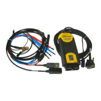
Fig. 5 – Multi-Diag Scope connection to Notebook through RS
232. Variant 3.
Fig. 6 – Multi-Diag Scope connection through USB using USB-
RS 232 converter. Variant 3.
Note: All device connectors shall be connected and disconnected with caution and without excessive
force!
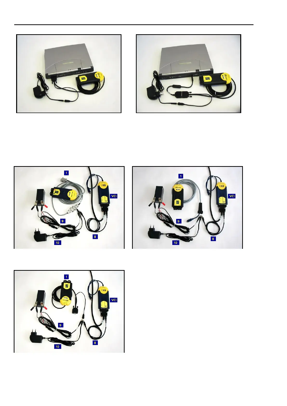
8. VARIANTS POWER SUPPLY OF MULTI-DIAG SCOPE
Fig. 7 – Power supply of Multi-Diag Scope – Variant 1 (oldest
version), VCI (vehicle communication interface) module is powered
through the OBD connector)
Fig. 8 – Power supply of Multi-Diag Scope – Variant 2, VCI
(vehicle communication interface) module is powered through the
OBD connector)
1 Multi-Diag Scope Interface (communication
interface)
8 Supply adaptor – vehicle communication
interface
9 Supply adaptor – battery / A
Supply adaptor – igniter
10 Network supply adaptor
Fig. 9 – Power supply of Multi-Diag Scope – Variant 3, VCI
(vehicle communication interface) module is powered through the
OBD connector)