Chap. I - Multi-Diag Scope Basic User’s Manual
Scope_manual_en-v110.docx — 18 —
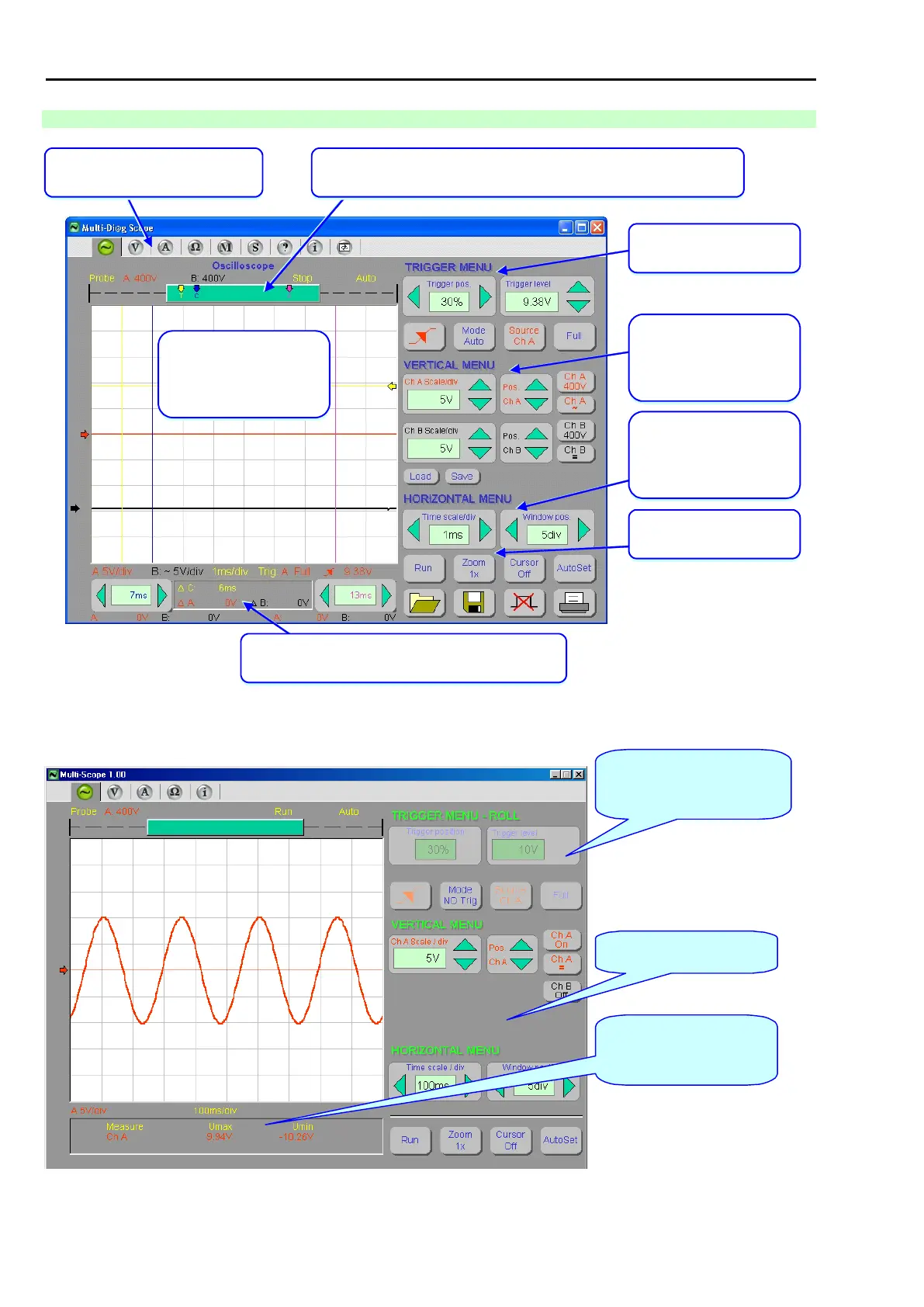
14.2.3 DESCRIPTION OF INDIVIDUAL PARTS
Visualization of set oscilloscope parameters, control of
cursors and results of cursor measurements
Control and setting of time
base and position of the
displayed part of the record
within the entire record.
Control and setting of input
sensitivity, input feedback,
record position and A and B
channel switch-off.
Window where scanned
courses, trigger position and
level and cursor position are
displayed
Selection of Multi-Diag Scope
individual functional modes
Record triggering control
and setting
Visualization of the position of the displayed part of the record, trigger level
position, and the position of cursors within the entire record
Fig. 36 – Description of individual parts of Multi-Diag Scope window in the Oscilloscope mode for two-channel measurement with
switched-on cursors (figure applies to version 7.3)
Value of the maximum and
minimum level of the
displayed signal.
Buttons with no significance for
the selected mode will change
their appearance (go blind).
Buttons for the switched-off
channel are not displayed.
Fig. 37 – Description of individual oscilloscope parts in the single-channel measurement in the Roll mode (figure applies to version 1.00)