Chap. II - Multi-Diag Motortester
Scope_manual_en-v110.docx — 57 —
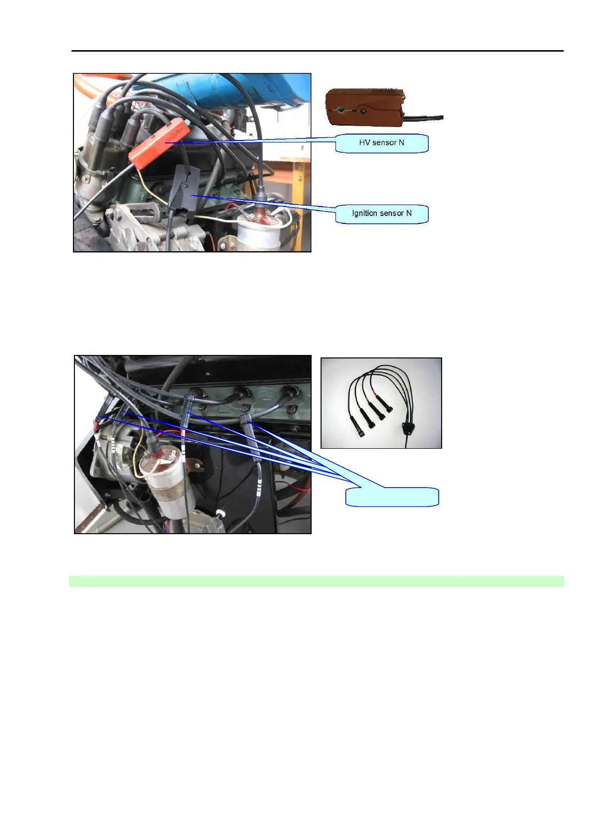
Fig. 128 – HV sensor N (AT111 4018)
5.4.1.2 HV SENSOR (AT111 4007)
For ignition systems containing ignition coil, distributor and HV cables. Connection examples can be found at Fig.
129.
Fig. 129 – HV sensor C4 (AT111 4007)
5.4.2 HV MEASUREMENT SYNCHRONIZATION
If you measure on one cylinder (see Fig. 130 and Fig. 131), the black ignition sensor and the HV sensor (in the
case of C4 sensor, there is only one HV sensor marked red) shall be connected to the cable of the measured
cylinder.
If you measure on more cylinders (see Fig. 132 to Fig. 135), it is important to mark the first cylinder in the firing
order with a black ignition sensor and to connect the grey ignition sensor so that its signal can inform the
motortester about the firing point of the other cylinders. If you measure on the single-coil ignition, the grey ignition
sensor shall be connected between the coil and the ignition distributor. If you measure on the twin-coil ignition,
the grey ignition sensor shall be connected to one of the cables leading from the second coil to which the black
ignition sensor is connected.
In some cases, it will be necessary to ensure the ignition source and the spark plug are connected via a suitable
cable for the connection of sensors.