Chap. II - Multi-Diag Motortester
Scope_manual_en-v110.docx — 60 —
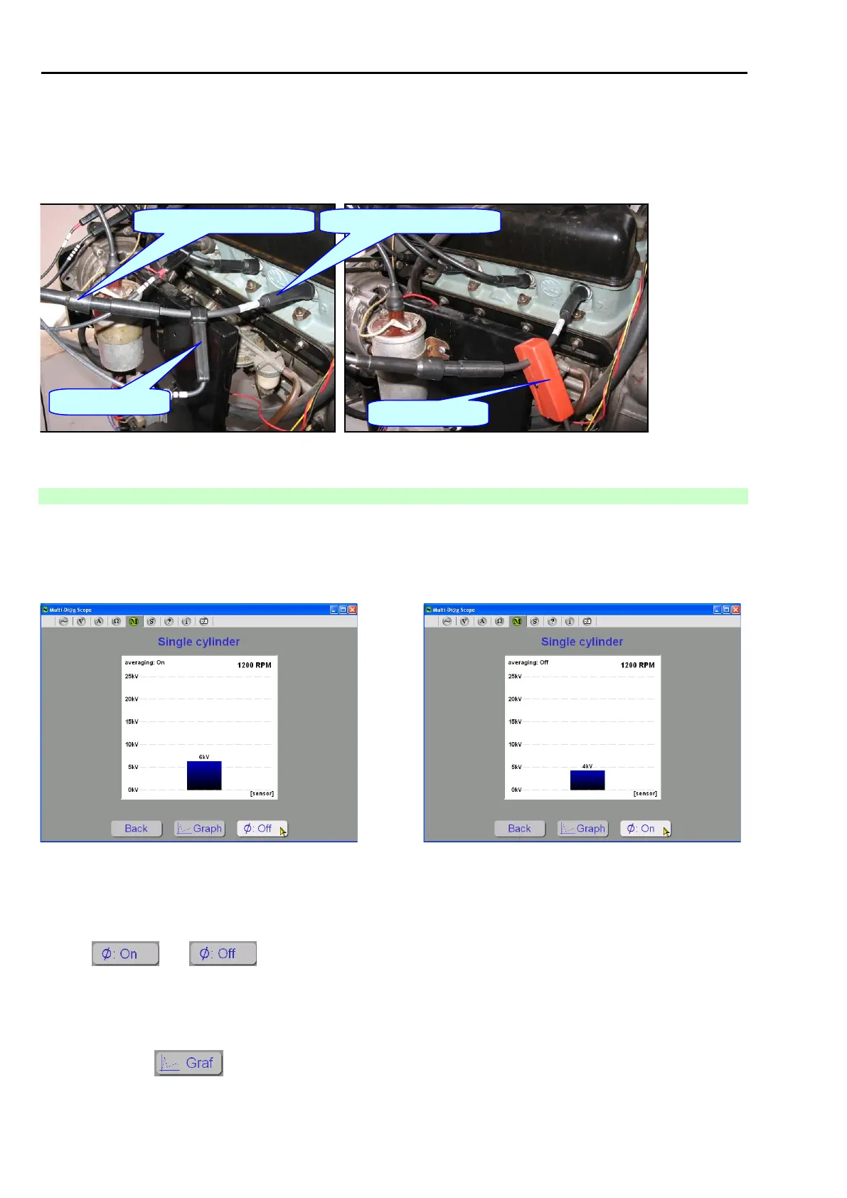
5.4.2.3 MEASUREMENT OF SPARK VOLTAGE ON THE REFERENCE HIGH-VOLTAGE
In case when very accurate values of spark voltage are required High-voltage reference cable (AT111 4056)
should be inserted between spark and its cable. The appropriate sensor is then placed on this reference cable
(see Fig. 136 for examples).
High-voltage reference cable
Fig. 136 – Placement of high-voltage sensors C4 and N on reference cable
5.4.3 SINGLE CYLINDER MEASUREMENT
The oscilloscope is set to optimum values as a default.
This type of measurement is suitable for ignition systems with HV cables. If this function is selected, a high voltage
bar chart for a single cylinder is displayed (see Fig. 137 or Fig. 138).
Fig. 137 – Single cylinder measurement – average of the last 4 samples
(default setting)
Fig. 138 – Single cylinder measurement
NOTE FOR FIG. 137 AND FIG. 138 (ACCOUNT OF BUTTONS ON / OFF):
Buttons and switch on and off the averaging of the last four measurement samples. Current
state is displayed (see Fig. 137 or Fig. 138).
The bar chart displays the present peak high voltage value on the selected cylinder. The engine speed is displayed
in the top right-hand corner (if the speed sensor is connected correctly).
By clicking on the button, you go to the oscilloscope measurement of the HV course (see Fig. 139).