Chap. III - Special tests
Scope_manual_en-v110.docx — 74 —
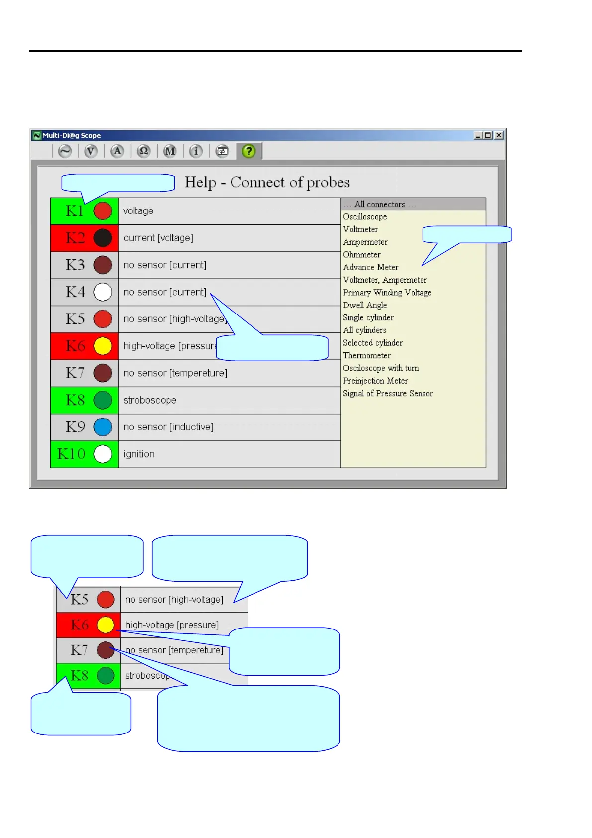
selected measurement highlighted in the list. The active connector has its indication circle in color, inactive
connectors (those that are not important for the respective measurement) are grey, see Fig. 170.
The option …All connectors … is general – it does not depend on the measurement type and activates all.
Connected probe
information
Fig. 168 – Main Help screen – Sensor connection
Green box
Probe correctly connected to
the connector
Grey box
No probe is connected to the
connector
Red box
Incorrectly connected probe
and its identification
Brown circle
Colour indication of Motortester connectors
serves for a better orientation when connecting
individual probes which also have a colour
mark on their cables
[ text in square brackets ]
Probe that should be connected to the
connector
Fig. 169 – Main Help screen – Sensor connection