2/11
A 200
About leak detection
GB 03302 - Edition 03 - July 12
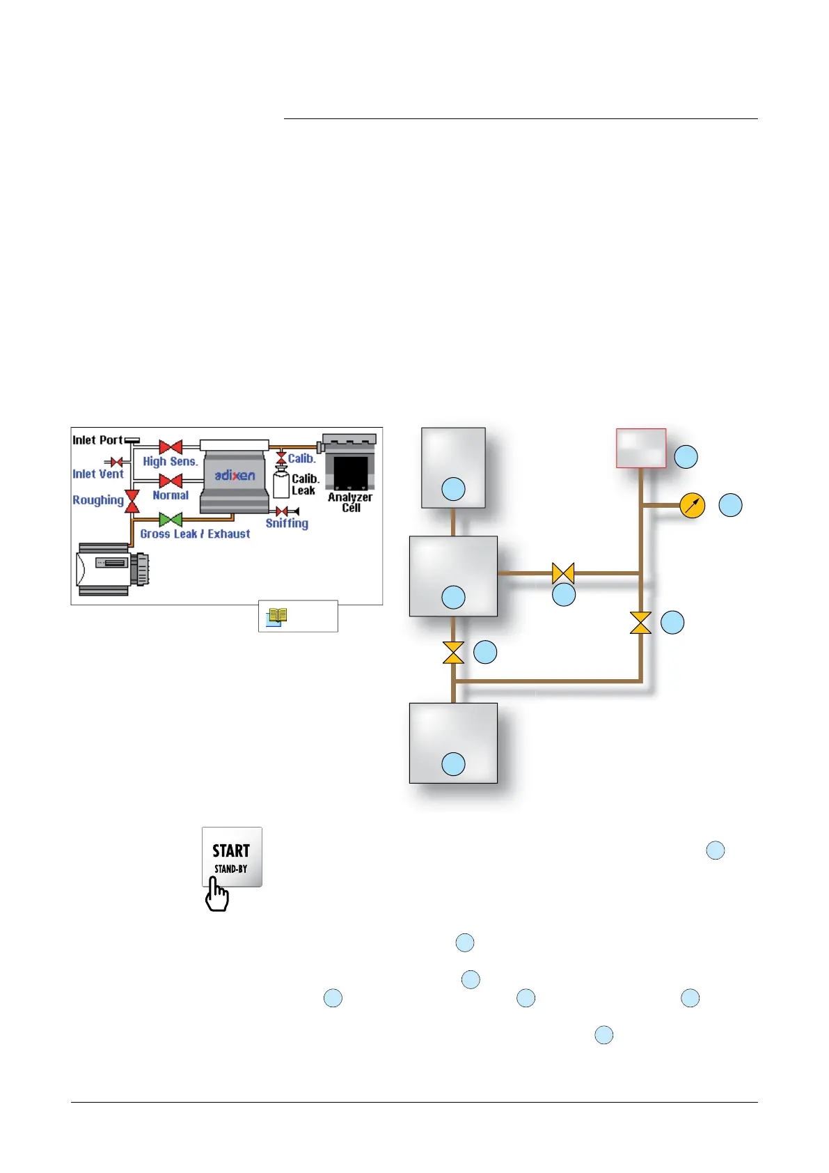
The general vacuum diagram of the leak detector is shown below.
A dynamic version of the vacuum diagram is available on the leak
detector display panel. Green valves indicate opened valves. Red
valves indicate closed valves.
Vacuum circuit of a
leak detector
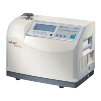
Test Procedure:
n Connect the part to be tested at the inlet of the leak detector
1
,
then press the [START/Stand by] key.
When the unit is not in test mode (stand-by or roughing mode), the
helium displayed corresponds to the internal helium background of the
unit.
n Roughing Mode: Valve
3
opens and the primary pump evacuates
the inlet of the unit as well as the part connected to it.
n When the inlet pressure
2
reaches the test cross over, the roughing
valve
3
closes, the exhaust valve
6
opens, the test valve
4
opens.
The high vacuum is then connected to the inlet of the leak detector
taking care of the gas load. The analyzer cell
8
will measure any
helium present. The value of the leak will be measured and displayed
on the control panel.
analyzer
cell
tested
part
8
6
secondary
pumping
exhaut
valve
7
primary
pumping
5
3
4
1
2
roughing
valve
test
valve
inlet pressure
gauge
inlet
C 200
General vacuum circuit
of a leak detector
Vacuum circuit of
the ASM 310
adixen Vacuum Products - ASM 310 Operating instructions