GB 04543 - Edition 02 - March 12
1/2
B 302
15 pin Interface
Purpose
The 15 pin Input/Output interface allows to control the leak
detector with a programmable logic controller or any other external
control device.
It also allows to get back a 0 - 10 V signal (1 V/decade)
corresponding to the leak flow measurement.
Connection
Refer to
B 400.
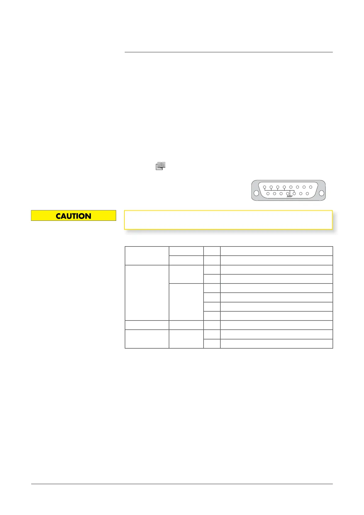
The 15 pin male connector and its cover
are supplied with the leak detector.
It is recommended to use a shielded cable which is grounded on the
connector cover.
Use
9 15
1 8
14
Inputs Digital 14 Cycle start
Analog 5 Not activated
Outputs Digital 6 Selected test mode reached
7 Reject point threshold crossed
Analog 9 Mantissa (0/10 V)*
10 He signal (logarithmic) (*)
11 Not activated
12 Exponent (0/10 V)
Ground 1 - 2 - 3 - 4 - 13
Headphones 8 Headphones +
(1)
15 Headphones -
(1)
(*) By default ; Adjustable by the user.
(1) To activate audio/headphones output, it is necessary to send "=HPD"RS 232
command to the leak detector : this command deactivates the loudspeaker.
To deactivate audio/headphones output, it is necessary to send "=HPE" RS 232
command to the leak detector : this command activates again the loudspeaker.
adixen Vacuum Products - ASM 310 Operating instructions